CTM-LBI-BR-U-AZ-V05-168249 (Order no. 168249)
Choose content
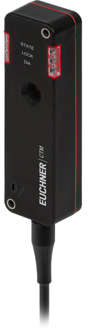
Safety switch with guard locking CTM-LBI-BR BiState, RFID, connection cable, connecting cable PVC
- BiState (bistable guard locking)
- Unicode
- Door position monitoring output/communication OD/C
- Connection cable, connecting cable PVC, 5m, flying lead
- Actuating/extraction/retention force: 20/18/5 N
- Auxiliary release
Description
BiState (bistable guard locking)
The device has a function that prevents
- people from accidentally becoming trapped in the event of a power failure or when the machine is switched off and the safety door is open
- the activated guard locking is deactivated in the event of a power failure.
Unicode evaluation
Each actuator is highly coded (unicode). The switch detects only taught-in actuators. Additional actuators can be taught-in.
Only the last actuator taught-in is detected.
Auxiliary release
The auxiliary release on the front allows access to the machine in the event of a malfunction, e.g. a power failure.
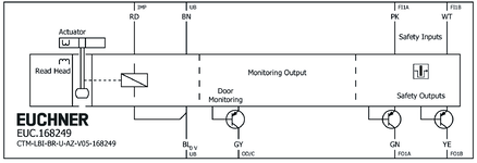
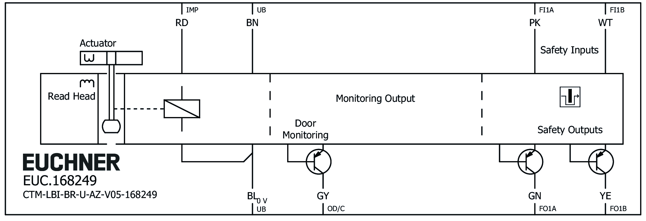
Terminal assignment
| Designation | Function | Connecting cable conductor coloring |
|---|---|---|
| FI1B | Enable input, channel B | WH |
| UB | Electronics and solenoid operating voltage, 24 V DC | BN |
| FO1A | Safety outputs channel A  | GN |
| FO1B | Safety outputs channel B | YE |
| OD/C | Door position monitoring output/communication | GY |
| FI1A | Enable input, channel A | PK |
| 0VUB | Electronics and solenoid operating voltage, 0 V DC | BU |
| IMP | Solenoid control input, 24 V DC | RD |
Accessories required
Actuator is not included.
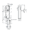
Dimensional drawings
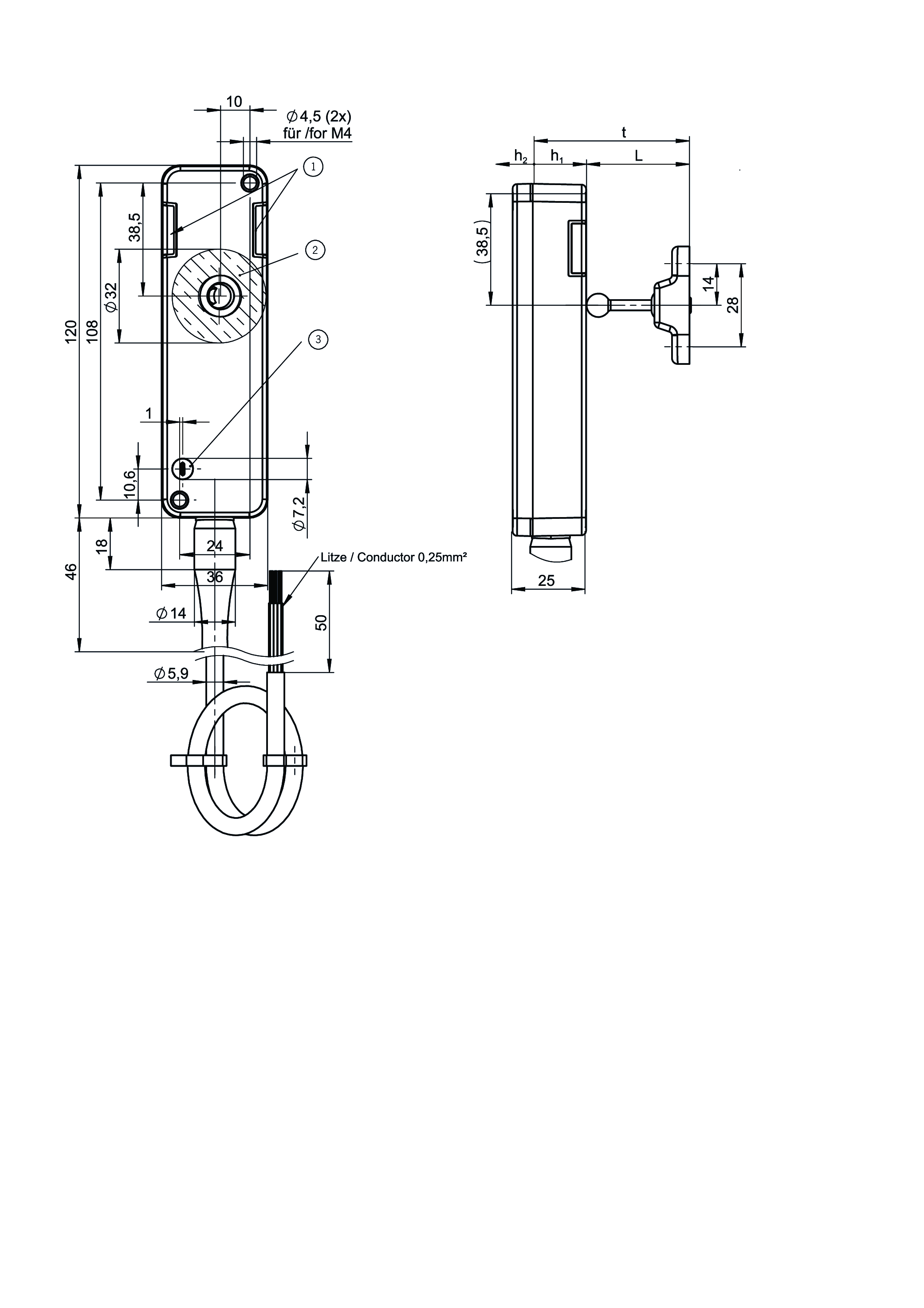
| 1 | LEDs |
| 2 | Active read head face |
| 3 | Auxiliary release (optional) |
Connection examples
Technical data
Approvals


Workspace
| Repeat accuracy R | 10 % |
Electrical connection values
| Fuse | |
| external (operating voltage UB) | 0.7 ... 8 A |
| Power consumption | |
| at max. switching frequency | 3 W |
| Rated insulation voltage Ui | 50 V |
| Rated impulse voltage Uimp | 0.5 kV |
| Discrepancy time | |
| both safety outputs | max. 10 ms Acc. to EN IEC 60947-5-3 |
| Turn-on time | max. 400 ms |
| Solenoid duty cycle | 100 % |
| Off-state current Ir | max. 0.25 mA |
| Risk time according to EN 60947-5-3 | max. 200 ms |
| Risk time according to EN 60947-5-3, extension for each additional device | max. 10 ms |
| Switching load | DC 24V, UL Class 2 (alternatively, see operating instructions) |
| Safety class | III |
| Test pulse duration | max. 0.3 ms |
| Test pulse interval | 100 ms |
| Degree of contamination (external, according to EN 60947-1) | 3 |
| Solenoid IMP | |
| Input voltage | |
| Guard locking active (closed) | 0 ... 5 V DC |
| Guard locking not active (open) | 20.4 ... 26.4 V DC |
| Current consumption | |
| Guard locking not active (open) | 20 ... 50 mA |
| Monitoring output OD/C | |
| Output type | p-switching, short circuit-proof |
| Output voltage | 0.8xUB ... UB V DC |
| Switching current | 1 ... 50 mA |
| Safety input 1 | |
| Current consumption | max. 7 mA Safety inputs Fl1A/Fl1B |
| Safety outputs FO1A/FO1B | |
| Output type | 2 semiconductor outputs, p-switching, short circuit-proof |
| Output voltage | |
| HIGH U(FO1A) / U(FO1B) | UB-1.5 ... UB V DC |
| LOW U(FO1A) / U(FO1B) | 0 ... 1 V DC |
| Discrepancy time | Acc. to EN IEC 60947-5-3 |
| Utilization category | |
| DC-13 | 24V 150mA (Caution: outputs must be protected with a free-wheeling diode in case of inductive loads) |
| Electrical switching frequency | max. 0.25 Hz |
| Switching current | |
| per safety output FO1A / FO1B | 1 ... 150 mA |
| Operating voltage UB | |
| Operating voltage DC | |
| UUB | 24 V DC -15% ... +15% reverse polarity protected, regulated, residual ripple<5%, PELV |
| Current consumption | |
| IUB at operating voltage UB = 24 V | max. 500 mA |
Mechanical values and environment
| Anfahrgeschwindigkeit | max. 20 m/min |
| Connection type | Connecting cable |
| Extraction force | 18 N |
| Ready delay | 5.5 s |
| Actuating force | 20 N |
| Installation orientation | any |
| Switching frequency | max. 0.25 Hz |
| Storage temperature | -25 ... 70 °C |
| Mechanical life | 1 x 10⁶ |
| Overtravel | 2 mm |
| Retention force | 5 N |
| Shock and vibration resistance | Acc. to EN IEC 60947-5-3 |
| Degree of protection | IP65/IP67/IP69K (screwed tight, plug connector/mating component. Please observe the notes in the operating instructions when using high-pressure cleaners.) |
| Ambient temperature | |
| at UB = 24 V DC | -20 ... 60 °C |
| Material | |
| Encapsulation | Technomelt PA6208 black |
| Seals | Fluorinated rubber (FKM) |
| Safety switch housing | Reinforced thermoplastic |
| Cable sheath | PVC |
| Locking force Fmax | 1300 N |
| Locking force FZh | 1000 N |
| Guard locking principle | BiState |
Characteristic values according to EN ISO 13849-1 and EN IEC 62061
| PL | Maximum SIL | PFHD | Category | Mission time | |
|---|---|---|---|---|---|
| Control of guard locking | PL d | 2 | 1.03x10⁻⁷ | 3 | 20 y |
| Guard lock monitoring | PL e | 3 | 4.11x10⁻⁹ | 4 | 20 y |
Miscellaneous
| Notices for UL approval | Operation only with UL Class 2 power supply or equivalent measures; see operating instructions |
Accessories


Downloads
Complete package
Download all important documents with a single click.
Content:
- The operating instructions and any additions to the operating instructions or brief instructions
- Any data sheets to supplement the operating instructions
- The declaration of conformity
Download Complete Package (ZIP, 5,6 MB)
Single Documents

Declarations of conformity
EU-Konformitätserklärung

Doc. no.
Version
Language
Size
EU-Konformitätserklärung
Doc. no.
EDC2525461
Version
Language
Size
0,5 MB
UKCA-Konformitätserklärung

Doc. no.
Version
Language
Size
UKCA-Konformitätserklärung
Doc. no.
EDC20001477
Version
Language
Size
0,1 MB
Instructions
Operating Instructions Transponder-Coded Safety Switch with Guard Locking CTM-LBI-BP/BR Unicode/Multicode with control of guard locking via control input IMP


Doc. no.
Version
Language
Size
Operating Instructions Transponder-Coded Safety Switch with Guard Locking CTM-LBI-BP/BR Unicode/Multicode with control of guard locking via control input IMP
Doc. no.
2525462
Version
10/24
Language
Size
2,8 MB
Mode d’emploi Interrupteur de sécurité à codage par transpondeur avec interverrouillage CTM-LBI-BP/BR Uni-/multicode avec commande de l’interverrouillage via l’entrée de commande IMP
Doc. no.
2525462
Version
10/24
Language
Size
2,8 MB
Manual de instrucciones Interruptor de seguridad codificado por transponder con bloqueo CTM-LBI-BP/BR Unicode/Multicode con accionamiento del bloqueo a través de la entrada de control IMP
Doc. no.
2525462
Version
10/24
Language
Size
2,8 MB
Betriebsanleitung Transpondercodierter Sicherheitsschalter mit Zuhaltung CTM-LBI-BP/BR Uni-/Multicode mit Ansteuerung der Zuhaltung über den Steuereingang IMP
Doc. no.
2525462
Version
10/24
Language
Size
2,8 MB
Návod k použití Bezpečnostní spínač s kódovaným transpondérem a jištěním ochranného krytu CTM-LBI-BP/BR Unicode/Multicode s ovládáním jištění ochranného krytu prostřednictvím řídicího vstupu IMP
Doc. no.
2525462
Version
10/24
Language
Size
2,9 MB

Other Documents
Approvals and certificates
FCC

Doc. no.
Version
Language
Size
FCC
Doc. no.
Version
Language
Size
0,1 MB
ISED

Doc. no.
Version
Language
Size
ISED
Doc. no.
Version
Language
Size
1,2 MB
Information EU Data Act

Doc. no.
Version
Language
Size
Information EU Data Act
Doc. no.
ECO20001824
Version
Language
Size
0,1 MB
UQS CTM…BI…

Doc. no.
Version
Language
Size
UQS CTM…BI…
Doc. no.
ECO20001463
Version
Language
Size
0,2 MB
WEEE

Doc. no.
Version
Language
Size
WEEE
Doc. no.
ECO20001806
Version
Language
Size
0,1 MB
c UL us

Doc. no.
Version
Language
Size
c UL us
Doc. no.
Version
Language
Size
0,3 MB
Ordering data
| Ordernumber | 168249 |
| Item designation | CTM-LBI-BR-U-AZ-V05-168249 |
| Gross weight | 0,55kg |
| Customs tariff number | 85365019000 |
| ECLASS | 27-27-24-05 Safety-related transponder switch with guardlocking |
