STM2N-2422B024-L01-M-172830 (Order no. 172830)
Safety switch STM Pro, cable entry M20 x 1.5
- Actuating head made of plastic
- Auxiliary release
- LED indicator
- Cable entry M20 x 1.5
- Open-circuit current principle

Description
Approach direction

Horizontal and vertical
Can be adjusted in 90° steps
Guard locking principle
Open-circuit current (power on to lock): On a guard with guard locking based on the open-circuit current principle, the guard is locked until the power supply to the guard locking solenoid is interrupted. Unlocking is by spring force. The term electrical guard locking is also used.
LED indicator
The LED indicator illuminates when voltage is applied to the guard locking solenoid.
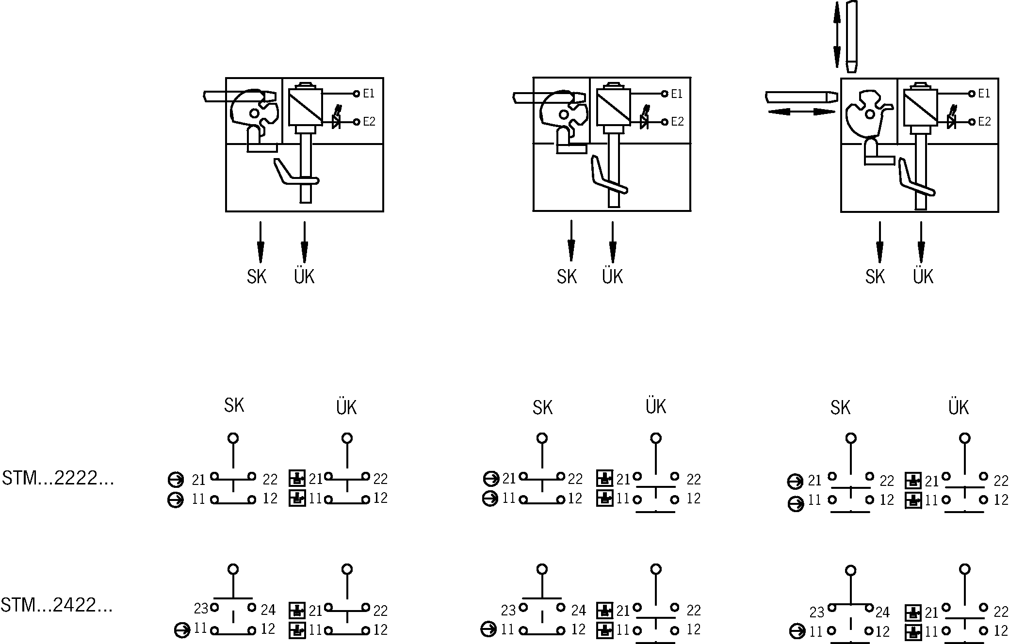
Switching element
2422 | Slow-action switching contact |
Contacts for guard locking: 2 positively driven contacts | |
Contacts for door monitoring: 1 positively driven contact |

 + 1 NO contact
Auxiliary release
The auxiliary release on the front makes it possible to access the machine if there is a malfunction, e.g. a power failure. Unlocking is performed using a tool or a key. The auxiliary release must be protected against misuse (sealing, lacquer).
Scope of delivery
Cable gland included.
Accessories required
Actuator is not included.
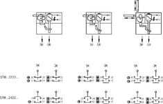
Functional drawings
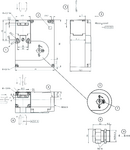
Dimensional drawings
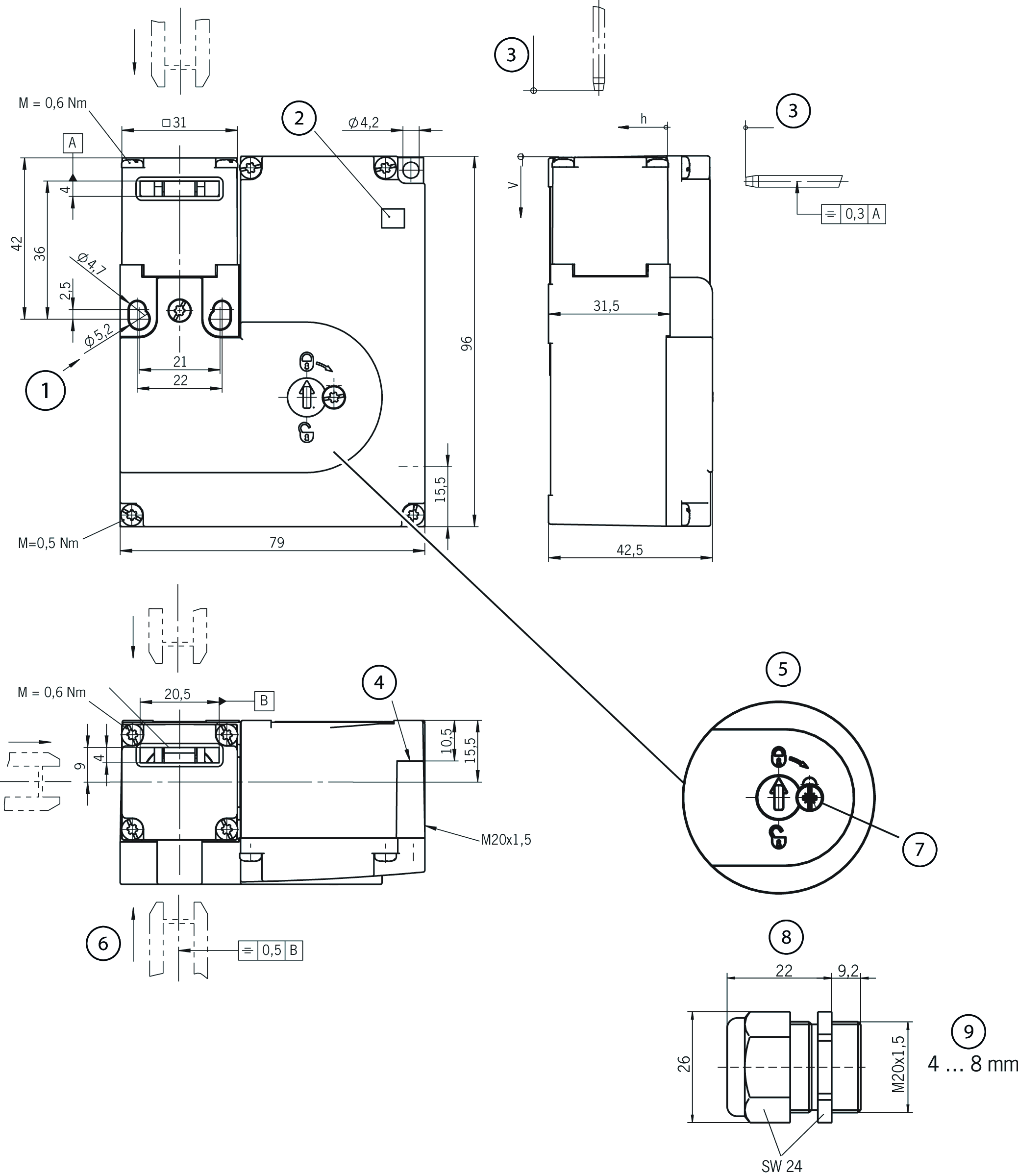
| 1 | Screw M5 for fixed positioning for safety applications |
| 2 | LED |
| 3 | Insertion depth |
| 4 | Protection against twisting (screw M4) |
| 5 | Auxiliary release |
| 6 | Actuator S standard |
| 7 | Locking screw (M = 0.5 Nm) |
| 8 | Cable gland |
| 9 | Cable diameter |
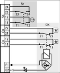
Connection examples

Technical data
Approvals

Electrical connection values
| Fuse | max. 4 A gG |
| Power consumption | 6 W |
| Connection cross section | 0.34 ... 1.5 mm² |
| Rated insulation voltage Ui | 250 V |
| Rated impulse voltage Uimp | 2.5 kV |
| Utilization category | |
| DC-13 | 4 A 24 V |
| AC-15 | 4 A 24 V |
| Solenoid operating voltage | |
| AC/DC | 24 V -15% ... +10% |
| Solenoid duty cycle | 100 % |
| Switching voltage | |
| min. at 10 mA | 12 V |
| Switching current | |
| min. at 24 V | 1 mA |
| thermal rated current Ith | 4 A |
Mechanical values and environment
| Anfahrgeschwindigkeit | max. 20 m/min |
| Approach direction | B |
| Connection type | |
| 1 x | M20 x 1.5 |
| Number of door position NO contacts | 1 |
| Number of door position positively driven contacts | 1 |
| Number of guard lock monitoring positively driven contacts | 2 |
| Extraction force | 30 N |
| Actuation frequency | max. 1200 1/h |
| Actuating force | 35 N |
| Installation orientation | any |
| Insertion depth | 24.5 mm |
| Storage temperature | -25 ... 70 °C |
| Mechanical life | 2 x 10⁶ |
| Retention force | 20 N |
| Switching principle | Slow-action switching contact |
| Degree of protection | IP67 |
| Ambient temperature | -20 ... 55 °C |
| Material | |
| Housing | Reinforced thermoplastic |
| Contact | Silver alloy, gold flashed |
| Locking force Fmax | 1000 N |
| Locking force FZh | 700 N |
| Guard locking principle | Open-circuit current principle |
Characteristic values according to EN ISO 13849-1 and EN IEC 62061
| B10D | Mission time | |
|---|---|---|
| Monitoring of the guard position | 2x10⁶ | 20 y |
| Important! Values valid at DC-13 100 mA/24V | ||
| Guard lock monitoring | 2x10⁶ | 20 y |
| Important! Values valid at DC-13 100 mA/24V | ||
In combination with actuator ACTUATOR-S-GT-SN
| Overtravel | 5 mm |
Accessories


Downloads
Complete package
Download all important documents with a single click.
Content:
- The operating instructions and any additions to the operating instructions or brief instructions
- Any data sheets to supplement the operating instructions
- The declaration of conformity
Single Documents


Other Documents


Ordering data
| Ordernumber | 172830 |
| Item designation | STM2N-2422B024-L01-M-172830 |
| Gross weight | 0,kg |
| Customs tariff number | 85365019000 |
| ECLASS | 27-27-26-03 Safety switch with guard control |
