MGBS-P-L1-AP-U-R-AEE-SH-174342 (Order no. 174342)
Choose content
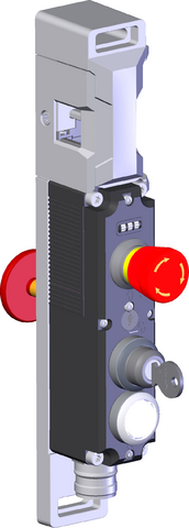
MGBS-AP, M23, EMERGENCY STOP, key-operated rotary switch, pushbutton, with guard locking, door hinge right
- Locking module (order handle module separately)
- Adjustable door hinge; factory setting: right
- Short circuit monitoring
- 2 safety outputs (semiconductor outputs)
- Up to category 4 / PL e according to EN ISO 13849-1
- Emergency stop
- 1 key-operated rotary switch 1 x 90°, form V
- incl. 2 keys (Id. No. 174553)
- 1 pushbuttons (illuminated)
- With plug connector M23
- Unicode
- Door position monitoring output
- With escape release (order inner door handle separately)
Description
Door hinge
The door hinge can be changed.
Unicode evaluation
Each handle module is highly coded (unicode). The locking module detects only handle modules that have been taught-in. Additional handle modules can be taught-in. Only the last handle module taught-in is detected.
Guard locking type
MGBS-L1 | Guard locking actuated by spring force and power-ON released (closed-circuit current principle). |
Lens set
The color of the pushbuttons can be selected using the color cover set included (5 colors).
Escape release
It is used for manual release of the guard locking without tools in an emergency. The inner door handle permits escape from the danger zone.
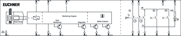
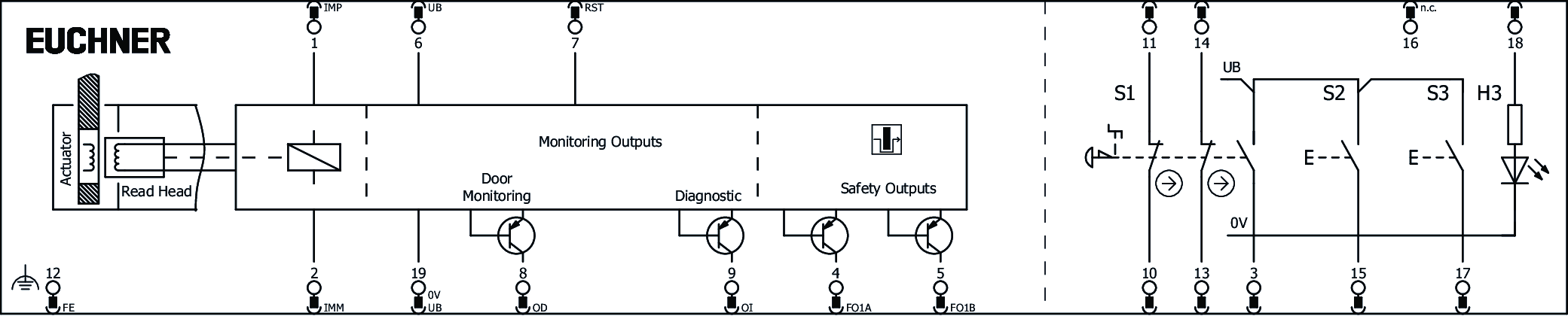
Connector assignment
| Plug connector (view of connection side) | Pin | Designation | Function | Connecting cable conductor coloring |
|---|---|---|---|---|
 | 1 | IMP | Solenoid operating voltage, 24 V DC | VT |
| 2 | IMM | Solenoid operating voltage, 0 V DC | RD | |
| 3 | S1.C | EMERGENCY STOP (monitoring contact) | GY | |
| 4 | FO1A | Safety output, channel A | RD/BU | |
| 5 | FO1B | Safety output, channel B | GN | |
| 6 | UB | Electronics operating voltage, 24 V DC | BU | |
| 7 | RST | Reset input | GY/PK | |
| 8 | OD | Door position monitoring output | GN/WH | |
| 9 | OI | Diagnostic monitoring output | YE/WH | |
| 10 | S1.A1 | EMERGENCY STOP (channel A) | GY/WH | |
| 11 | S1.A2 | EMERGENCY STOP (channel A) | BK | |
| 12 | FE | Functional earth (must be connected to meet the EMC requirements) | GN/YE | |
| 13 | S1.B1 | EMERGENCY STOP (channel B) | PK | |
| 14 | S1.B2 | EMERGENCY STOP (channel B) | BN/GY | |
| 15 | S2 | Key-operated rotary switch 2 | BN/YE | |
| 16 | n.c. | n.c. | BN/GN | |
| 17 | S3 | Pushbutton 3 (illuminated) | WH | |
| 18 | H3 | LED 3 | YE | |
| 19 | 0VUB | Operating voltage electronics, controls/indicators 0 V DC | BN |
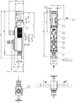
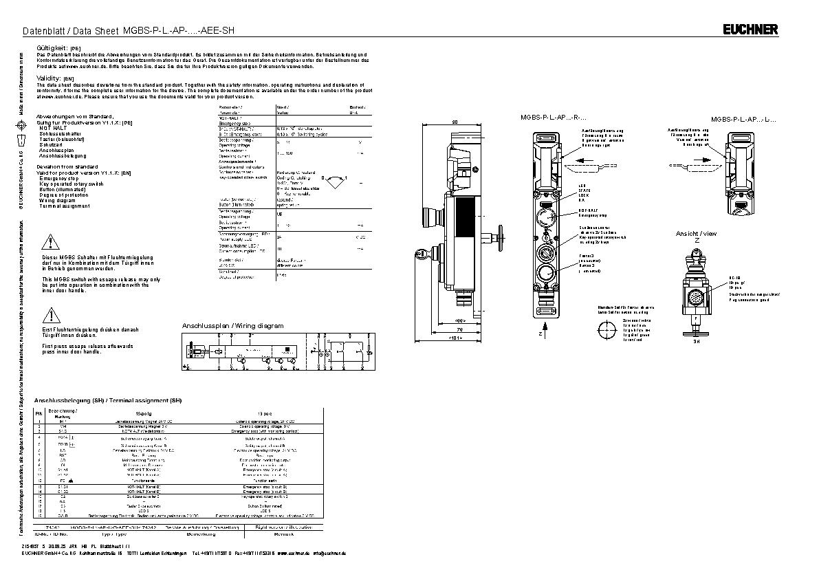
Dimensional drawings
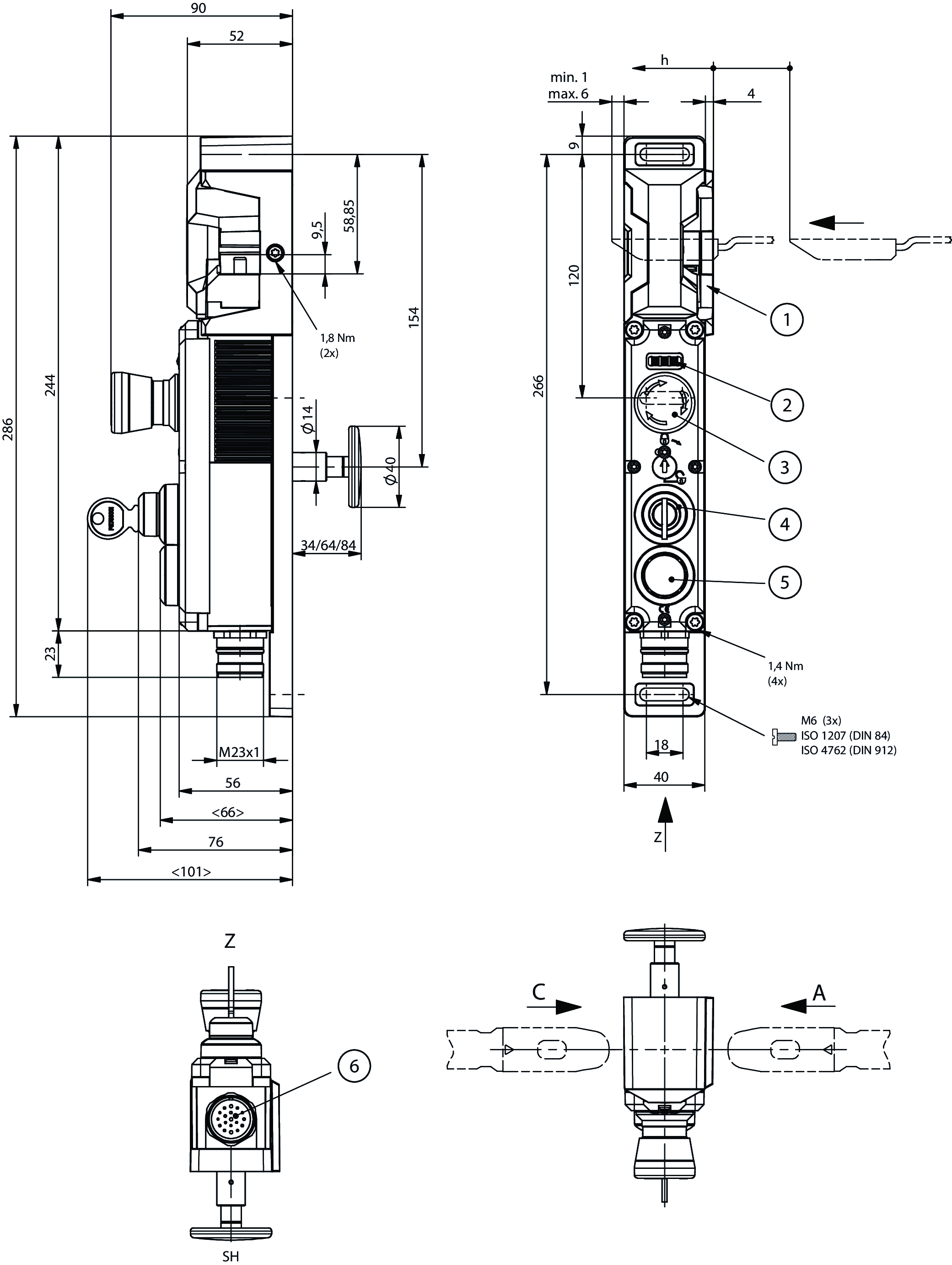
| 1 | Door hinge right |
| 2 | LEDs |
| 3 | EMERGENCY STOP |
| 4 | Key-operated rotary switch |
| 5 | Pushbutton 3 |
| 6 | M23 (plug connector(s) adjusted) |
Connection examples
Technical data
Approvals


Workspace
| Repeat accuracy R | |
| according to EN 60947-5-2 | 10 % |
Operating and display elements
| Item | Color | Extras | Note slide-in label | Version | Slide-in label | Switching element | Number | Designation1 | LED |
|---|---|---|---|---|---|---|---|---|---|
| 1 | Emergency stop | 2 PD | |||||||
| 2 | Key-operated rotary switch | 1NO | |||||||
| 3 | Illuminated pushbutton | 1NO |
Electrical connection values
| Fuse | |
| external (operating voltage UB) | 0.25 ... 8 A |
| external (solenoid operating voltage IMP) | 0.5 ... 8 A |
| Power consumption | 6 W |
| Rated insulation voltage Ui | 50 V |
| Rated impulse voltage Uimp | 0.5 kV |
| Operating voltage DC | |
| UUB | 24 V DC -15% ... +15% reverse polarity protected, regulated, residual ripple<5%, PELV |
| EMC protection requirements | Acc. to EN IEC 60947-5-3 |
| Utilization category | |
| DC-13 | 24V 150mA (Caution: outputs must be protected with a free-wheeling diode in case of inductive loads) |
| Solenoid operating voltage DC | |
| UIMP | 24 V DC -15% ... +10% reverse polarity protected, regulated, residual ripple<5%, PELV |
| Solenoid duty cycle | 100 % |
| Switching load | |
| according to UL | 24V DC, Class 2 (alternatively, see operating instructions) |
| Safety class | III |
| Current consumption | |
| IUB | 40 mA |
| IIMP | 400 mA |
| Test pulse duration | max. 0.3 ms (Applies to a load with C<= 30nF and R<= 20kOhm) |
| Test pulse interval | min. 100 ms |
| Degree of contamination (external, according to EN 60947-1) | 3 |
| Controls and indicators | |
| Operating voltage | UB V |
| Operating current | 1 ... 50 mA |
| Power supply | |
| LED | 24 V |
| Current consumption | |
| LED | 10 mA |
| Emergency stop | |
| Breaking capacity | max. 0.25 W |
| Switching voltage | 5 ... 24 V |
| Switching current | 1 ... 100 mA |
| Monitoring output OD, OI, S1.C | |
| Output type | p-switching, short circuit-proof |
| Output voltage | 0.8xUB ... UB V DC |
| Switching current | 1 ... 50 mA |
| Safety outputs FO1A/FO1B | |
| Output type | 2 semiconductor outputs, p-switching, short circuit-proof |
| Output voltage | |
| HIGH U(FO1A) / U(FO1B) | UB-1.5 ... UB V DC |
| LOW U(FO1A) / U(FO1B) | 0 ... 1 V DC |
| Discrepancy time | |
| both safety outputs | max. 10 ms Acc. to EN IEC 60947-5-3 |
| Turn-on time | max. 400 ms |
| Off-state current Ir | max. 0.25 mA |
| Switching current | |
| per safety output FO1A / FO1B | 1 ... 150 mA |
Mechanical values and environment
| Anfahrgeschwindigkeit | max. 20 m/min |
| Connection type | 1 plug connector M23, 19-pin, RC18 |
| Extraction force | 20 N |
| Ready delay | max. 1 s |
| Actuating force | 10 N |
| Installation orientation | Door hinge DIN right |
| Switching frequency | max. 0.5 Hz |
| Storage temperature | -25 ... 70 °C |
| Mechanical life | 1 x 10⁶ |
| Overtravel | 5 mm |
| Retention force | 20 N |
| Shock and vibration resistance | Acc. to EN IEC 60947-5-3 |
| Degree of protection | IP65 (screwed tight plug connector/mating component) |
| Ambient temperature | |
| at UB = 24 V DC | -20 ... 55 °C |
| Material | |
| Safety switch housing | Reinforced thermoplastic |
| Switch bracket | Die-cast zinc |
| Locking force Fmax | 3900 N |
| Locking force FZh | 3000 N (Fzh = Fmax/1.3, depending on the actuator used) |
| Guard locking principle | Closed-circuit current principle |
Characteristic values according to EN ISO 13849-1 and EN IEC 62061
| PL | Maximum SIL | PFHD | Category | Mission time | |
|---|---|---|---|---|---|
| Guard lock monitoring | PL e | - | 4.1x10⁻⁹ | 4 | 20 y |
| B10D | Mission time | |
|---|---|---|
| Emergency stop | 0.13x10⁶ | 20 y |
| PL | Maximum SIL | Category | Mission time | |
|---|---|---|---|---|
| Control of guard locking | Depending on external control of guard locking | 20 y | ||
Miscellaneous
| Notices for UL approval | Operation only with UL Class 2 power supply or equivalent measures; see operating instructions |
| Additional feature | |
| incl. key Id. No. 174553 | |
| Escape release actuated by pushing | |
| incl. lens set, ID no. 120344 |
Accessories
Connection material
Connecting cable with plug connector M23 with option C1825, 1.5 m, angled

092906
C-M23F19-19XDIFPU01,5-MA-092906
C-M23F19-19XDIFPU01,5-MA-092906
- M23 plug connector, 18-pin + PE
- Angled plug connector
- Cable exit C (left)
- PUR cable
- Cable length 1.5 m
- With flying lead
- Cores color-coded
092907
C-M23F19-19XDIFPU01,5-MA-092907
C-M23F19-19XDIFPU01,5-MA-092907
- M23 plug connector, 18-pin + PE
- Angled plug connector
- Cable exit A (right)
- PUR cable
- Cable length 1.5 m
- With flying lead
- Cores color-coded
Connecting cable with plug connector M23 with option C1825, 10 m, angled
092901
C-M23F19-19XDIFPU10,0-MA-092901
C-M23F19-19XDIFPU10,0-MA-092901
- M23 plug connector, 18-pin + PE
- Angled plug connector
- Cable exit C (left)
- PUR cable
- Cable length 10 m
- With flying lead
- Cores color-coded
092902
C-M23F19-19XDIFPU10,0-MA-092902
C-M23F19-19XDIFPU10,0-MA-092902
- M23 plug connector, 18-pin + PE
- Angled plug connector
- Cable exit A (right)
- PUR cable
- Cable length 10 m
- With flying lead
- Cores color-coded
Connecting cable with plug connector M23 with option C1825, 15 m, angled
077020
C-M23F19-19XDIFPU15,0-MA-077020
C-M23F19-19XDIFPU15,0-MA-077020
- M23 plug connector, 18-pin + PE
- Angled plug connector
- Cable exit C (left)
- PUR cable
- Cable length 15 m
- With flying lead
- Cores color-coded
085196
C-M23F19-19XDIFPU15,0-MA-085196
C-M23F19-19XDIFPU15,0-MA-085196
- M23 plug connector, 18-pin + PE
- Angled plug connector
- Cable exit A (right)
- PUR cable
- Cable length 15 m
- With flying lead
- Cores color-coded
Connecting cable with plug connector M23 with option C1825, 20 m, angled
092910
C-M23F19-19XDIFPU20,0-MA-092910
C-M23F19-19XDIFPU20,0-MA-092910
- M23 plug connector, 18-pin + PE
- Angled plug connector
- Cable exit C (left)
- PUR cable
- Cable length 20 m
- With flying lead
- Cores color-coded
092911
C-M23F19-19XDIFPU20,0-MA-092911
C-M23F19-19XDIFPU20,0-MA-092911
- M23 plug connector, 18-pin + PE
- Angled plug connector
- Cable exit A (right)
- PUR cable
- Cable length 20 m
- With flying lead
- Cores color-coded
Connecting cable with plug connector M23 with option C1825, 25 m, angled
092912
C-M23F19-19XDIFPU25,0-MA-092912
C-M23F19-19XDIFPU25,0-MA-092912
- M23 plug connector, 18-pin + PE
- Angled plug connector
- Cable exit C (left)
- PUR cable
- Cable length 25 m
- With flying lead
- Cores color-coded
092913
C-M23F19-19XDIFPU25,0-MA-092913
C-M23F19-19XDIFPU25,0-MA-092913
- M23 plug connector, 18-pin + PE
- Angled plug connector
- Cable exit A (right)
- PUR cable
- Cable length 25 m
- With flying lead
- Cores color-coded
Connecting cable with plug connector M23 with option C1825, 3 m, angled
092908
C-M23F19-19XDIFPU03,0-MA-092908
C-M23F19-19XDIFPU03,0-MA-092908
- M23 plug connector, 18-pin + PE
- Angled plug connector
- Cable exit C (left)
- PUR cable
- Cable length 3 m
- With flying lead
- Cores color-coded
092909
C-M23F19-19XDIFPU03,0-MA-092909
C-M23F19-19XDIFPU03,0-MA-092909
- M23 plug connector, 18-pin + PE
- Angled plug connector
- Cable exit A (right)
- PUR cable
- Cable length 3 m
- With flying lead
- Cores color-coded
Connecting cable with plug connector M23 with option C1825, 6 m, angled
077018
C-M23F19-19XDIFPU06,0-MA-077018
C-M23F19-19XDIFPU06,0-MA-077018
- M23 plug connector, 18-pin + PE
- Angled plug connector
- Cable exit C (left)
- PUR cable
- Cable length 6 m
- With flying lead
- Cores color-coded
085194
C-M23F19-19XDIFPU06,0-MA-085194
C-M23F19-19XDIFPU06,0-MA-085194
- M23 plug connector, 18-pin + PE
- Angled plug connector
- Cable exit A (right)
- PUR cable
- Cable length 6 m
- With flying lead
- Cores color-coded
Connecting cable with plug connector M23 with option C1825, 8 m, angled
077019
C-M23F19-19XDIFPU08,0-MA-077019
C-M23F19-19XDIFPU08,0-MA-077019
- RC18 plug connector, 18-pin + PE
- Angled plug connector
- Cable exit C (left)
- PUR cable
- Cable length 8 m
- With flying lead
- Cores color-coded
085195
C-M23F19-19XDIFPU08,0-MA-085195
C-M23F19-19XDIFPU08,0-MA-085195
- M23 plug connector, 18-pin + PE
- Angled plug connector
- Cable exit A (right)
- PUR cable
- Cable length 8 m
- With flying lead
- Cores color-coded


Downloads
Complete package
Download all important documents with a single click.
Content:
- The operating instructions and any additions to the operating instructions or brief instructions
- Any data sheets to supplement the operating instructions
- The declaration of conformity
Download Complete Package (ZIP, 14,7 MB)
Single Documents
Declarations of conformity
EU-Konformitätserklärung

Doc. no.
Version
Language
Size
EU-Konformitätserklärung
Doc. no.
EDC2123042
Version
Language
Size
0,2 MB
UKCA-Konformitätserklärung

Doc. no.
Version
Language
Size
UKCA-Konformitätserklärung
Doc. no.
EDC20001501
Version
Language
Size
0,1 MB
Instructions
Operating Instructions MGBS-P-L.-AP… Unicode/Multicode


Doc. no.
Version
Language
Size
Operating Instructions MGBS-P-L.-AP… Unicode/Multicode
Doc. no.
2527245
Version
06/23
Language
Size
4,3 MB
Mode d’emploi MGBS-P-L.-AP… Uni-/multicode
Doc. no.
2527245
Version
06/23
Language
Size
4,3 MB
Manual de instrucciones MGBS-P-L.-AP… Unicode/Multicode
Doc. no.
2527245
Version
06/23
Language
Size
4,3 MB
Betriebsanleitung MGBS-P-L.-AP… Uni-/Multicode
Doc. no.
2527245
Version
06/23
Language
Size
4,3 MB
Istruzioni di impiego MGBS-P-L.-AP… Unicode/Multicode
Doc. no.
2527245
Version
06/23
Language
Size
4,3 MB
操作説明書 MGBS-P‑L.‑AP… ユニコード/マルチコード
Doc. no.
2527245
Version
06/23
Language
Size
4,8 MB

Other Documents
Approvals and certificates
FCC

Doc. no.
Version
Language
Size
FCC
Doc. no.
Version
Language
Size
0,1 MB
IC

Doc. no.
Version
Language
Size
IC
Doc. no.
Version
Language
Size
1,8 MB
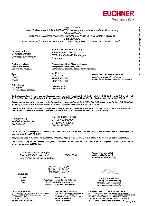
UQS CTP-AP-AR_MGBS-AP-AR_
Doc. no.
Version
Language
Size
UQS CTP-AP-AR_MGBS-AP-AR_
Doc. no.
ECO2123565
Version
Language
Size
0,2 MB
WEEE

Doc. no.
Version
Language
Size
WEEE
Doc. no.
ECO20001806
Version
Language
Size
0,1 MB
c UL us

Doc. no.
Version
Language
Size
c UL us
Doc. no.
Version
Language
Size
0,3 MB
Sales documents
Multifunctional Gate Box MGBS Slimline


Doc. no.
Version
Language
Size
Multifunctional Gate Box MGBS Slimline
Doc. no.
163691
Version
03-03/20
Language
Size
13,3 MB
Multifunctional Gate Box MGBS Slimline
Doc. no.
163692
Version
03-03/20
Language
Size
13,4 MB
Multifunctional Gate Box MGBS Slimline
Doc. no.
163693
Version
03-03/20
Language
Size
13,4 MB
Multifunctional Gate Box MGBS Slimline
Doc. no.
163690
Version
03-03/20
Language
Size
13,3 MB
製品/マルチファンクション-ゲート-ボックス- MGBS Slimline
Doc. no.
164508
Version
03-03/20
Language
Size
4,8 MB
Ordering data
| Ordernumber | 174342 |
| Item designation | MGBS-P-L1-AP-U-R-AEE-SH-174342 |
| Gross weight | 2,19kg |
| Customs tariff number | 85371098 |
| ECLASS | 27-27-24-05 Safety-related transponder switch with guardlocking |
