MGB-L2-APA-AA6A1-S3-R-110544 (Order no. 110544)
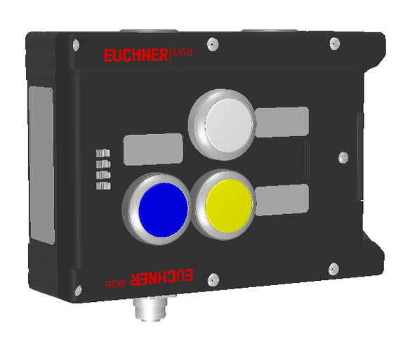
Locking module MGB-L2-APA.. (guard locking by solenoid force) with 3 pushbuttons, incl. label carrier, M12 for enabling switch
- Guard locking with guard lock monitoring
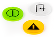
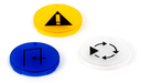
- 3 pushbuttons (illuminated, wh, ye, bu)
- incl. adhesive labels
- With cable entry
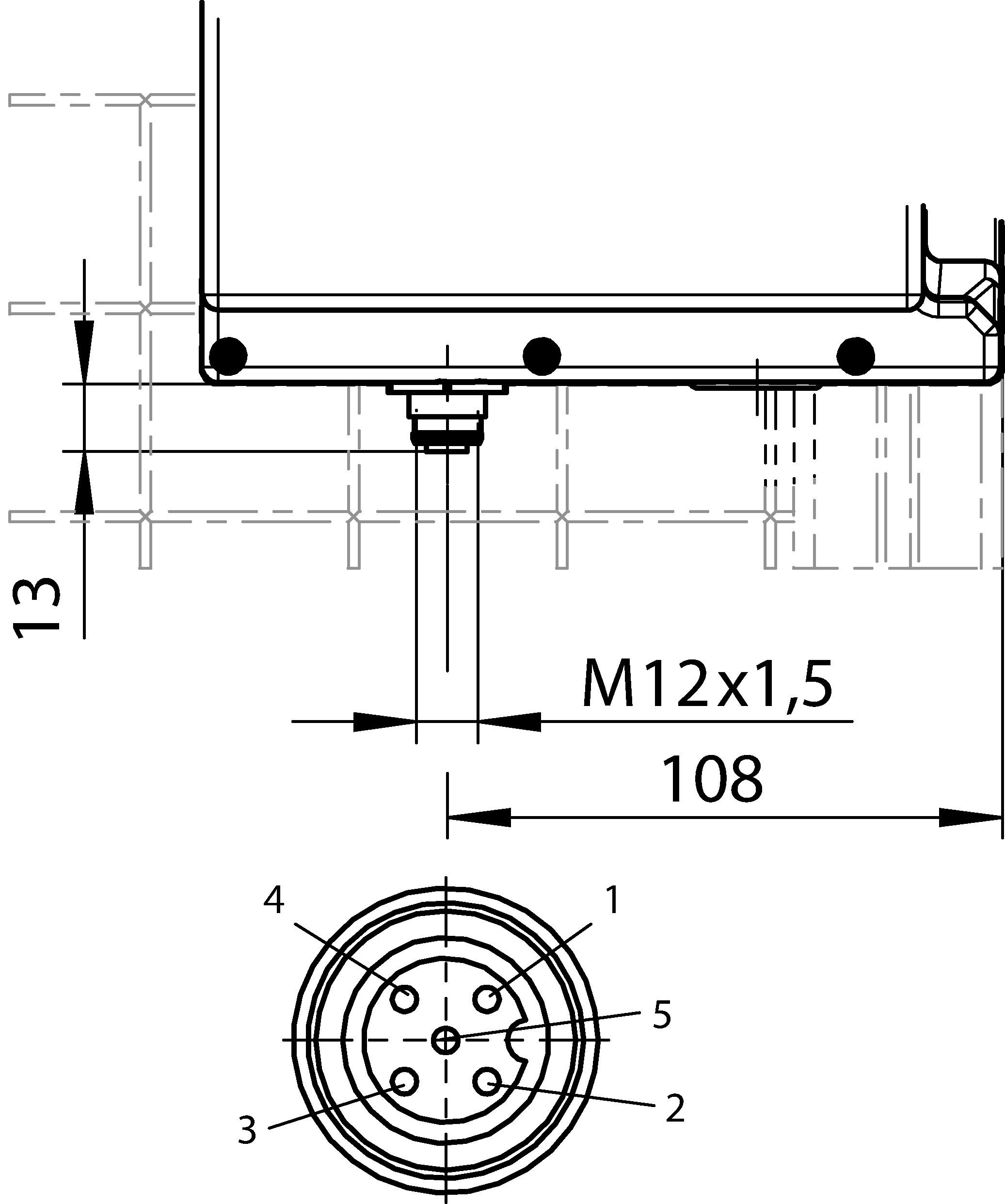
- With plug connector M12 for enabling switch
- Unicode
Description
Guard locking type
MGB-L2... | The locking arm is held in the locked position by solenoid force and is unlocked by spring force when the solenoid is switched off (open-circuit current principle, electrically locked). |
Door hinge
A mechanical door stop is permanently integrated into the evaluation module of the MGB. A marking on the stop makes adjustment easier.
LED indicator
The LED indicator indicates all important system and status information.
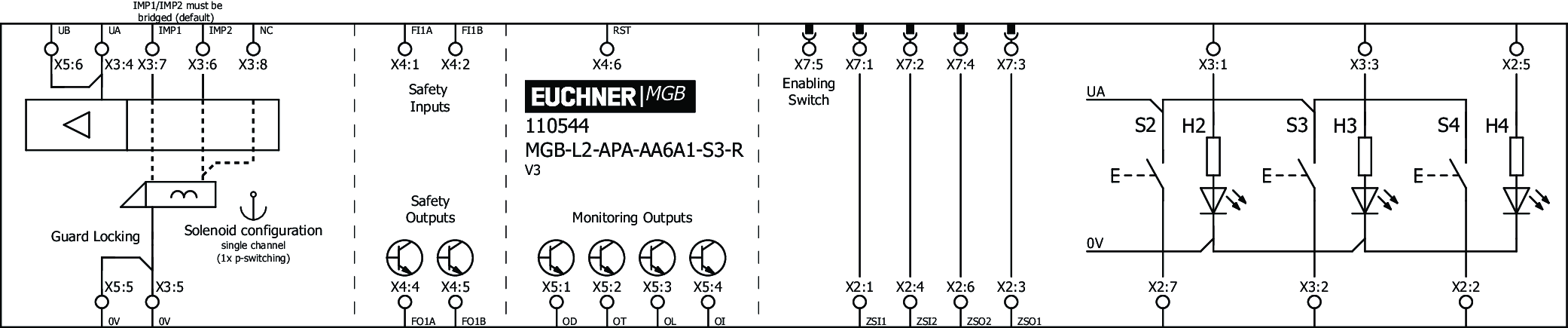
Monitoring outputs
OD | ON when the door is closed |
OT | Bolt tongue inserted into the evaluation module |
OL | Guard locking solenoid in locked position |
OI | Diagnostics; there is a fault |
Pushbuttons
S2 | 1 NO contact, white, illuminated |
S3 | 1 NO contact, yellow, illuminated |
S4 | 1 NO contact, blue, illuminated |
Connection for enabling switch
The device has an M12 plug connector for the direct connection of an enabling switch (e.g. ZSA, order no.: 110560).
Adhesive labels
Devices with adhesive labels have pre-formed recesses. The adhesive labels enclosed (standard size 12.5 x 27 mm) can be affixed in these recesses.

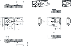
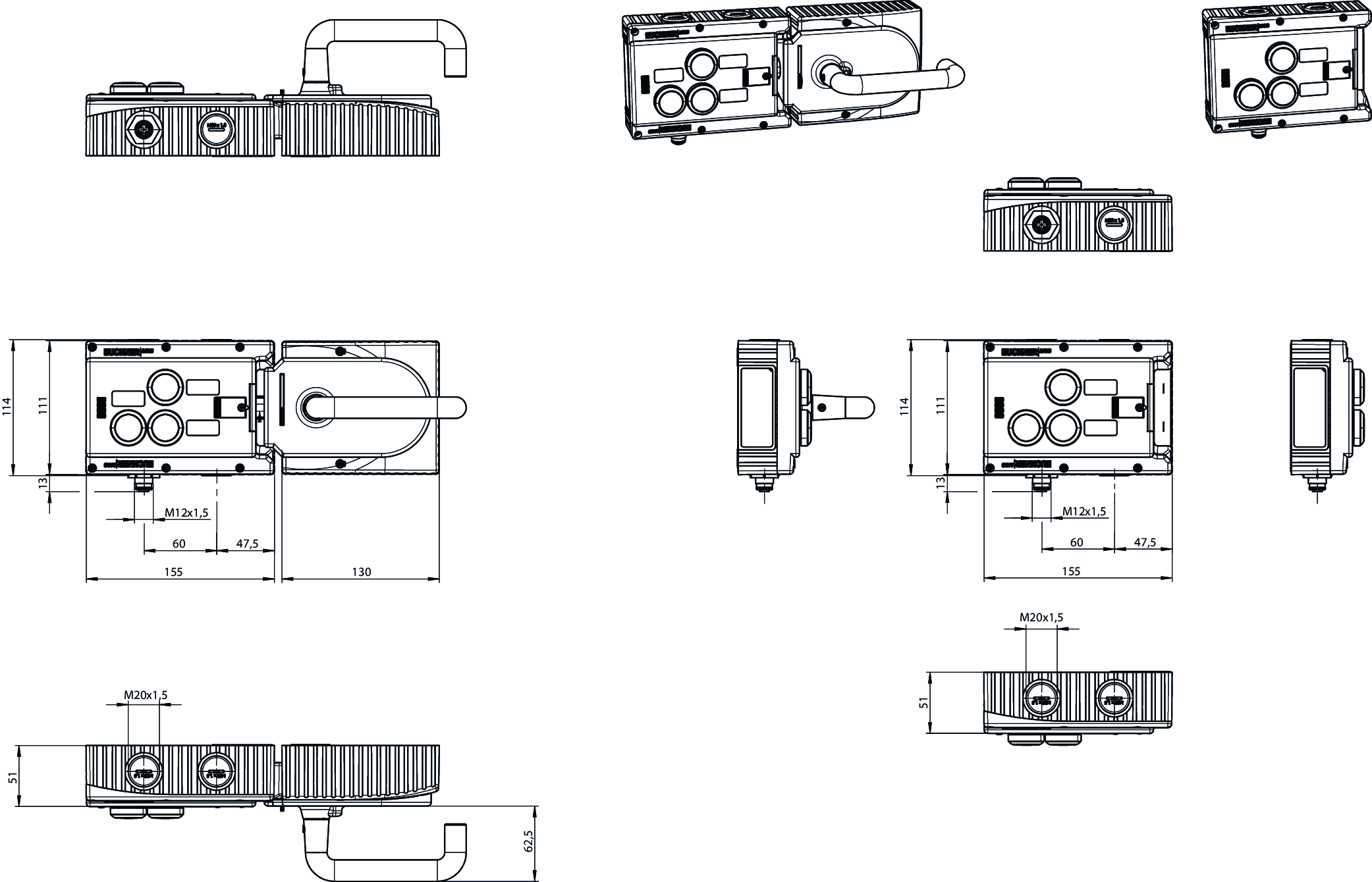
Dimensional drawings
Dimensional drawings
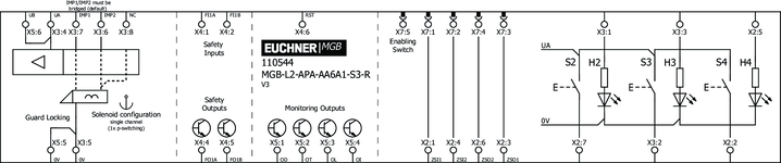
Connection examples
Technical data
Approvals


Operating and display elements
| Occupancy diagram | L1 |
| Item | Color | Extras | Note slide-in label | Version | Switching element | Slide-in label | Number | Designation1 | LED |
|---|---|---|---|---|---|---|---|---|---|
| 2 | white | Illuminated pushbutton | 1NO | ||||||
| 3 | yellow | Illuminated pushbutton | 1NO | ||||||
| 4 | blue | Illuminated pushbutton | 1NO |
Electrical connection values
| Connection cross section | |
| (rigid/flexible) | 0.13 ... 1.5 mm² ((AWG 24 ... AWG 16)) |
| (rigid/flexible) with cable end sleeve according to DIN 46 228/1 | 0.25 ... 1.5 mm² |
| (rigid/flexible) with cable end sleeve with collar according to DIN 46 228/1 | 0.25 ... 0.75 mm² |
| Rated insulation voltage Ui | 30 V |
| Rated impulse voltage Uimp | 1.5 kV |
| Discrepancy time | |
| between FO1A and FO1B | max. 10 ms |
| Utilization category | |
| DC-13 | 24V 200mA (Caution: outputs must be protected with a free-wheeling diode in case of inductive loads.) |
| Risk time according to EN 60947-5-3 | max. 350 ms |
| Safety class | III |
| Transponder coding | Unicode |
| Degree of contamination (external, according to EN 60947-1) | 3 |
| Solenoid control input IMP1, IMP2, IMM | |
| Test pulse duration | max. 5 ms |
| Test pulse interval | min. 100 ms |
| Controls and indicators | |
| Breaking capacity | max. 0.25 W |
| Switching voltage | UA V |
| Switching current | 1 ... 10 mA |
| LED power supply | 24 V DC |
| Monitoring outputs OD, OT, OL, OI | |
| Output type | Semiconductor outputs, p-switching, short circuit-proof |
| Output voltage | UA-2V ... UA V DC (Value at a switching current of 50mA without taking into account the cable lengths) |
| Output current | max. 50 mA |
| Safety outputs FO1A, FO1B | |
| Output type | Semiconductor outputs, p-switching, short circuit-proof |
| Output voltage | |
| UFO1A /UFO1B LOW | 0 ... 1 V DC |
| UFO1A /UFO1B HIGH | UB-2V ... UB V DC (Value at a switching current of 50mA without taking into account the cable lengths) |
| Output current | |
| per safety output FO1A / FO1B | 1 ... 200 mA |
| Test pulse duration | max. 0.3 ms |
| Test pulse interval | min. 100 ms |
| Power supply UA | |
| Operating voltage DC | |
| UA | 24 V DC -15% ... +10% ((reverse polarity protected, regulated, residual ripple<5%, PELV)) |
| Current consumption | |
| IUA | max. 375 mA ((with energized guard locking solenoid and unloaded outputs OD, OT, OL, OI, +20 °C, 24V)) |
| Power supply UB | |
| Operating voltage DC | |
| UB | 24 V DC -15% ... +10% ((reverse polarity protected, regulated, residual ripple<5%, PELV)) |
| Current consumption | |
| IUB | max. 80 mA ((no load on outputs)) |
Mechanical values and environment
| Connection type | |
| Cable entries M20x1.5 | |
| Plug connector SFF5 (X7) | |
| Installation orientation | Door hinge DIN right |
| Switching frequency | 0.25 Hz |
| Storage temperature | -25 ... 70 °C |
| Mechanical life | |
| 1 x 10⁶ | |
| in case of use as door stop, and 1 Joule impact energy | 0.1 x 10⁶ |
| Degree of protection | IP65 |
| Ambient temperature | |
| at UB = 24 V DC | -20 ... 55 °C |
| Material | |
| Housing | Fiber glass reinforced plastic; nickel-plated die-cast zinc; stainless steel |
| Locking force FZh | 2000 N |
| Guard locking principle | Open-circuit current principle |
Characteristic values according to EN ISO 13849-1 and EN IEC 62061
| PL | Maximum SIL | PFHD | Category | Mission time | |
|---|---|---|---|---|---|
| Monitoring of the guard position | PL e | - | 3.7x10⁻⁹ | 4 | 20 y |
| Guard lock monitoring | PL e | - | 3.7x10⁻⁹ | 4 | 20 y |
Miscellaneous
| Slide-in label | |||||||||||||||||||||||||
| |||||||||||||||||||||||||
| Product version number | V3.0.3 | ||||||||||||||||||||||||
Accessories


Downloads
Complete package
Download all important documents with a single click.
Content:
- The operating instructions and any additions to the operating instructions or brief instructions
- Any data sheets to supplement the operating instructions
- The declaration of conformity
Single Documents


Other Documents


Ordering data
| Ordernumber | 110544 |
| Item designation | MGB-L2-APA-AA6A1-S3-R-110544 |
| Gross weight | 1,032kg |
| Customs tariff number | 85371098 |
| ECLASS | 27-27-24-05 Safety-related transponder switch with guardlocking |
