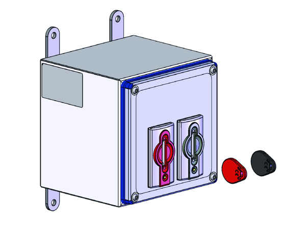
Euchner Control Box ECB
- Safe entry into hazardous areas
- Can be used as a trapped key system or as a safe lockout bar
- Two key adapters installed in housing
- Integrated evaluation units with two safe relay outputs, with pulsing for short-circuit monitoring
- Transponder-coded keys (unique)
- Control of bistable guard locking of CTP switches as a function of the key position (inserted/not inserted)
- Connection of the ECB via 2 x M12/8-pin plug connectors
Ismertetés
Note
Keys are included / order safety switch CTP including actuator separately
Functional description
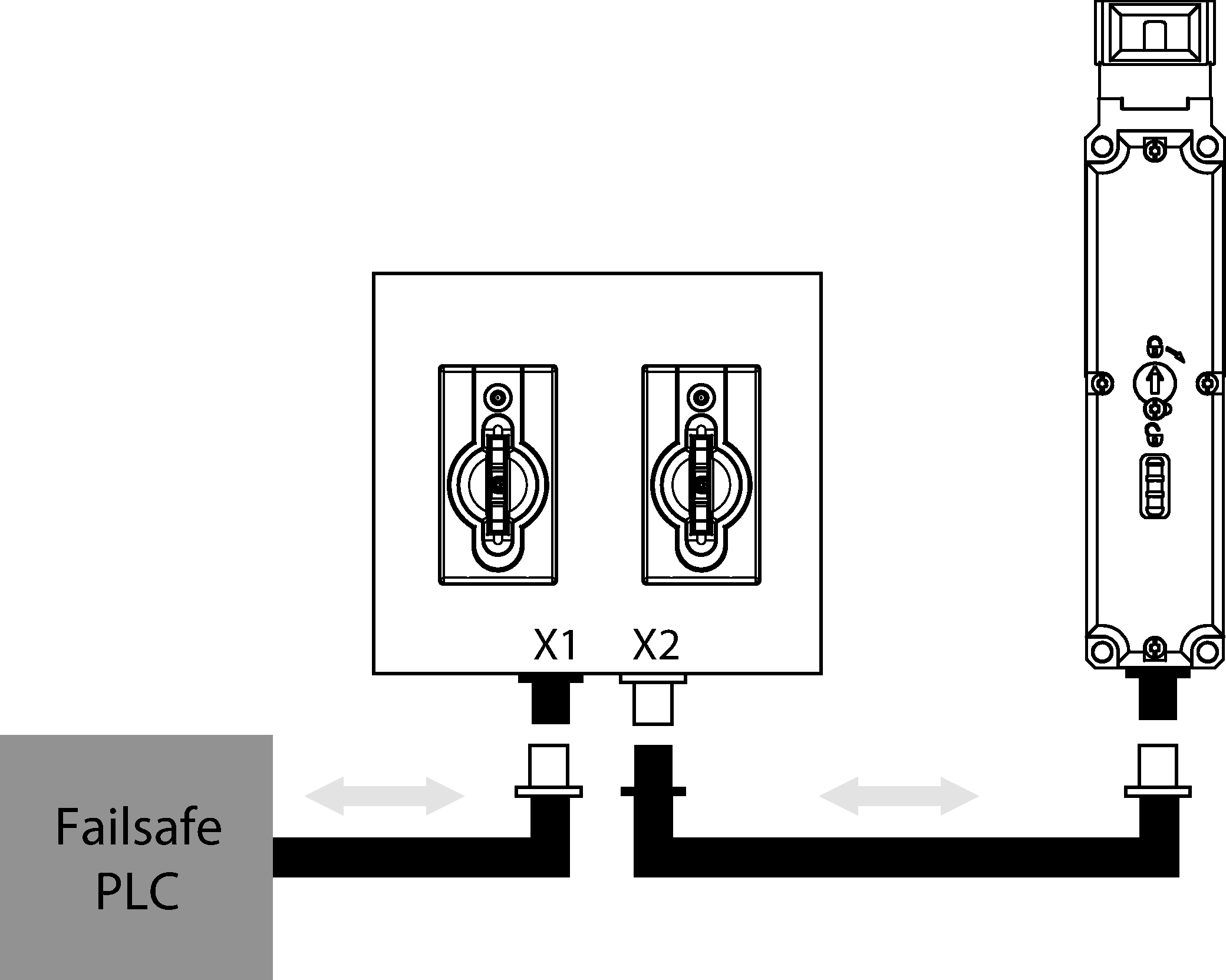
In combination with a control system, the Euchner Control Box allows dangerous machine movements to be performed as long as all valid unique, transponder-coded keys (CKS keys) are inserted. If at least one CKS key is removed during operation, the two safety contacts are switched off and a stop command is triggered. The safety contacts remain switched off when the CKS key is removed. The installation cannot be restarted.
Function as lockout bar
When the CKS keys are removed from an ECB device up to two persons can access the hazardous area for servicing. As long as the operator carries the CKS key with him, there is no hazard for the operator due to unexpected machine start-up or being locked into the machine unintentionally. The ECB therefore performs the function of a safe lockout bar. The system can fulfill its safety function only if the users always carry their CKS keys with them when accessing the machine.
Function as trapped key system
When the CKS key is removed, the operator can enter the hazardous area safely and can use the same CKS key to start local machine functions via another ECB device.
Control of guard locking
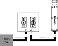
Version ECB-A-2K-A1-160397 of this device features the option of controlling the guard locking of a safety switch CTP-LBI-AP. Guard locking release is prevented on the connected safety switch as long as all CKS keys are inserted in the device. In this combination, guard locking fulfills only the requirements for process protection. The task of the ECB-A1 device is to ensure that guard locking can be released only if the following conditions are met simultaneously: - A PLC signal is present at input IMP. - At least one of the two CKS keys has been removed from the CKS key adapter. Guard locking of safety switch CTP-LBI-AP cannot be activated or moved to locked position as long as at least one of the CKS keys is removed. Safety outputs FO1A and FO1B of safety switch CTP-LBI-AP are switched off as long as guard locking is released. Safety switch CTP-LBI-AP additionally features a bistable guard locking function. It ensures that the guard locking remains in its most recent position in case of a power failure: either “locked” or “released.”
Safety characteristics according to EN ISO 13849-1
Monitoring of the CKS keys and the guard position (prevention of unexpected start-up of a machine when the key is removed and the door is open) Category 4 Performance Level (PL) e
Connector assignment
| Plug connector (view of connection side) | Pin | Designation | Function | |
|---|---|---|---|---|
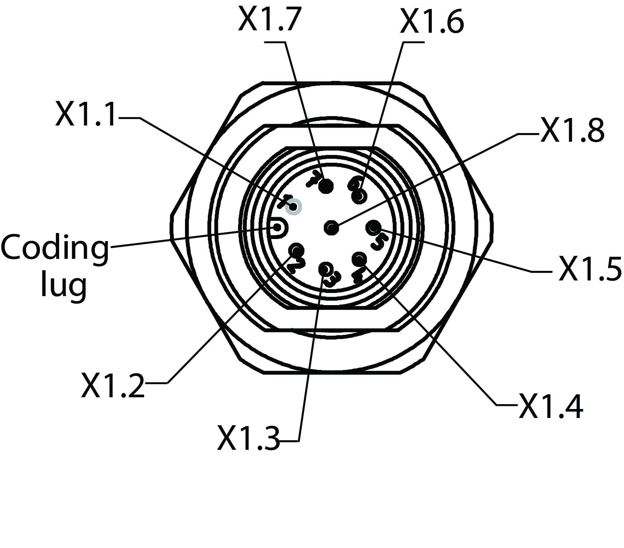 |  | X 1.1 | IMP | Control input of guard locking solenoid, 24 V DC |
| UB | Operating voltage, 24 V DC | |||
| 14 | Safety output, channel 1 | |||
| 25 | Safety output, channel 2 | |||
| OI | Diagnostic output | |||
| OD | Door monitoring output | |||
| OL | Guard lock monitoring output | |||
| 0 V UB | Operating voltage, 0 V DC | |||
| OMP | Control output for guard locking solenoid CTP, 24 V DC | |||
| UB | Operating voltage, 24 V DC | |||
| 13 | Connection for safety output CTP, channel 1 | |||
| 23 | Connection for safety output CTP, channel 2 | |||
| OI | Connection for diagnostic output CTP | |||
| OD | Connection for door monitoring output CTP | |||
| OL | Connection for guard lock monitoring output CTP | |||
| 0 V UB | Operating voltage, 0 V DC |
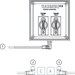
Connection examples
Connection examples
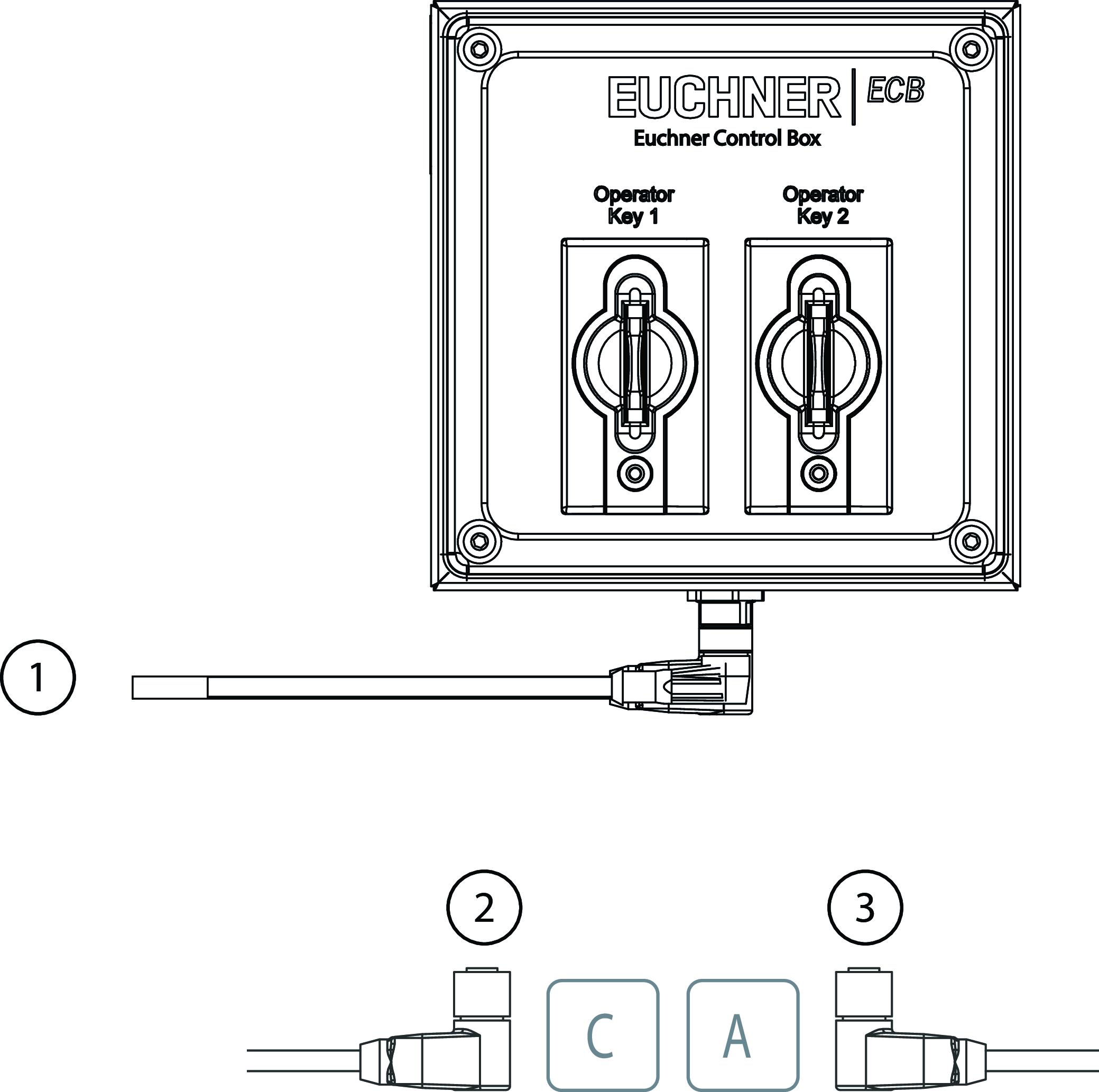
| 1 | X1: connection to PLC |
| 2 | Cable outlet C (left) |
| 3 | Cable outlet A (right) |
Műszaki adatok
Electrical connection values
| Fuse | |
| external (operating voltage UB) | 1.2 ... 8 A |
| external (safety circuit) according to EN 60269-1 | 6 A (6 AgG or 6 A circuit breaker (characteristic B or C)) |
| rated conditional short-circuit current | 100 A |
| Rated insulation voltage Ui | |
| DC | 75 V |
| Rated impulse withstand voltage Uimp | 0.5 kV |
| Operating voltage DC | |
| UB | 21 ... 24 ... 27 V DC (regulated, residual ripple<5%) |
| Discrepancy time | |
| between the operating points of both safety relays | max. 25 ms |
| EMC protection requirements | EN 60947-5-3 |
| Utilization category | |
| DC-13 | 24 V 150 mA |
| Switching current | |
| Semiconductor outputs | 10 ... 150 mA |
| Safety class | III |
| Current consumption | |
| with relay energized | 650 mA (without taking into account the load currents at the monitoring outputs) |
| Degree of contamination (external, according to EN 60947-1) | 3 |
Mechanical values and environment
| Dimensions | 160 x 160 x 150 |
| Connection type | 2 x plug connectors M12, 8-pin |
| Number of safety inputs | 2 semiconductor outputs of safety switch CTP-LBI-AP are connected in series with one relay contact each (relay with internally monitored contacts) |
| Ready delay | 10 ... 12 s (After the operating voltage is switched on, the relay outputs are switched off and the monitoring outputs are set to LOW level during the ready delay. For visual indication of the delay, the green STATE LED flashes at a frequency of approx. 15 Hz.) |
| Atmospheric humidity | |
| not condensing | max. 80 % rH |
| Shock and vibration resistance | Acc. to EN IEC 60947-5-3 |
| Degree of protection | IP65 |
| Ambient temperature | -20 ... +45 °C |
| Material | |
| Housing | Stainless steel 1.4301 |
| Housing seal | Silicone |
Characteristic values according to EN ISO 13849-1 and EN IEC 62061
| Monitoring of the CKS keys and the guard position | |
| Number of switching cycles | |
| ≤ 0.1 A | 760000 1/y |
| Diagnostic Coverage (DC) | 99 % |
| Mission time | 20 y (This value is dependent on the number of switching cycles and the switching current.) |
| Category | 4 (This value is dependent on the number of switching cycles and the switching current.) |
| Performance Level | PL e (This value is dependent on the number of switching cycles and the switching current.) |
| PFHD | |
| System | 2.3 x 10⁻⁸ (This value is dependent on the number of switching cycles and the switching current.) |
Miscellaneous
| The following applies to the approval according to UL | Operation only with UL Class 2 power supply or equivalent measures |
Tartozékok


Letöltések
Teljes csomag
Minden fontos dokumentum letöltése egyetlen kattintással.
Tartalom:
- A használati utasítás és a használati utasítás vagy a rövid utasítás kiegészítései
- A használati utasítást kiegészítő adatlapok
- A megfelelőségi nyilatkozat
Egyedi dokumentumok


Egyéb dokumentumok


Rendelési adatok
| Rend. sz. | 160397 |
| Cikk neve | ECB-A-2K-A1-160397 |
| Súly | 3,495kg |
| Vámtarifaszám | 85365019000 |