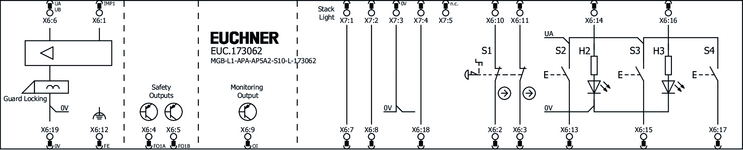
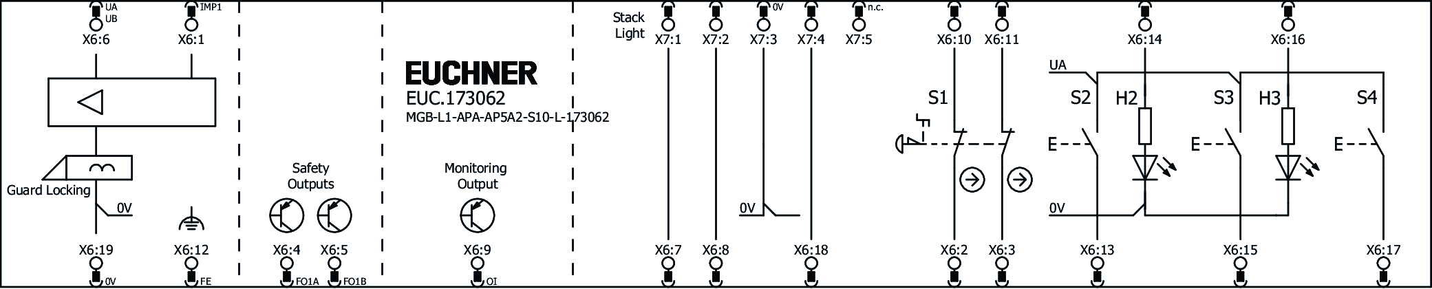
MGB-L1-APA-AP5A2-S10-L-173062 (Sip. No. 173062)
Choose content
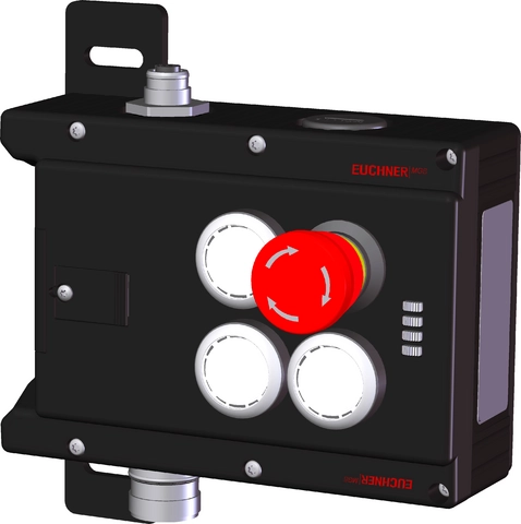
Locking module MGB-L1-APA.., (guard locking by spring force) with 3 pushbuttons, emergency stop, RC18, M12, on mounting plates
- Guard locking with guard lock monitoring
- Emergency stop according to ISO 13850
- 3 pushbuttons (illuminated)
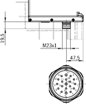
- With plug connector RC18
- With plug connector M12 for signal light
- Mounted on mounting plates
- Unicode
Açıklama
Guard locking type
MGB-L1... | The locking arm is held in the locked position by spring force and is unlocked by solenoid force (closed-circuit current principle, mechanically locked). |
Door hinge
A mechanical door stop is permanently integrated into the evaluation module of the MGB. A marking on the stop makes adjustment easier.
Monitoring outputs
OI | Diagnostics; there is a fault |
LED indicator
The LED indicator indicates all important system and status information.
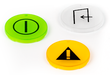
Emergency stop device
S1 | 2 positively driven contacts, emergency stop with turn-to-reset, not illuminated |
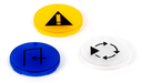
Pushbuttons
S2 | 1 NO contact, illuminated |
S3 | 1 NO contact, illuminated |
S4 | 1 NO contact, not illuminated |
Notice
The interlocking module is pre-assembled on a mounting plate.
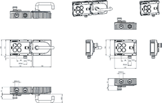
Dimensional drawings
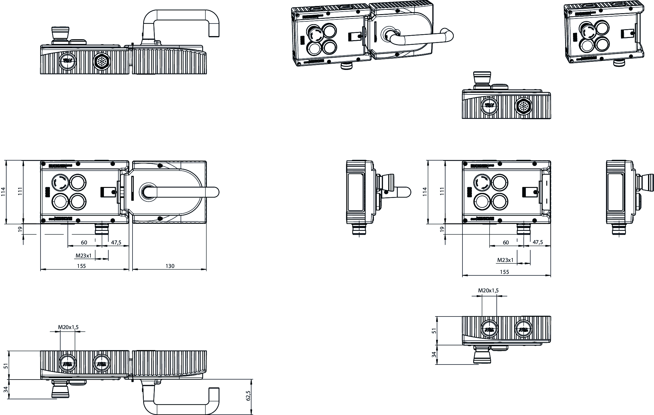
Dimensional drawings

Connection examples
Teknik Veriler
Approvals


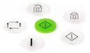
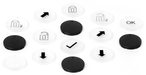
Operating and display elements
| Occupancy diagram | L1 |
| Item | Color | Extras | Slide-in label | Note slide-in label | Switching element | Version | Number | Designation1 | LED |
|---|---|---|---|---|---|---|---|---|---|
| 1 | 2 PD | Emergency stop | |||||||
| 2 | 1NO | Illuminated pushbutton | |||||||
| 3 | 1NO | Illuminated pushbutton | |||||||
| 4 | 1NO | Pushbutton, not illuminated |
Electrical connection values
| Rated insulation voltage Ui | 30 V |
| Rated impulse voltage Uimp | 1.5 kV |
| Discrepancy time | |
| between FO1A and FO1B | max. 10 ms |
| Utilization category | |
| DC-13 | 24V 200mA (Caution: outputs must be protected with a free-wheeling diode in case of inductive loads.) |
| Risk time according to EN 60947-5-3 | max. 350 ms |
| Safety class | III |
| Transponder coding | Unicode |
| Degree of contamination (external, according to EN 60947-1) | 3 |
| Solenoid control input IMP1, IMP2, IMM | |
| Test pulse duration | max. 5 ms |
| Test pulse interval | min. 100 ms |
| Controls and indicators | |
| Breaking capacity | max. 0.25 W |
| Switching voltage | UA V |
| Switching current | 1 ... 10 mA |
| LED power supply | 24 V DC |
| Emergency stop | |
| Breaking capacity | max. 0.25 W |
| Switching voltage | 5 ... 24 V |
| Switching current | 1 ... 100 mA |
| Monitoring outputs OD, OT, OL, OI | |
| Output type | Semiconductor outputs, p-switching, short circuit-proof |
| Output voltage | UA-2V ... UA V DC (Value at a switching current of 50mA without taking into account the cable lengths) |
| Output current | max. 50 mA |
| Safety outputs FO1A, FO1B | |
| Output type | Semiconductor outputs, p-switching, short circuit-proof |
| Output voltage | |
| UFO1A /UFO1B LOW | 0 ... 1 V DC |
| UFO1A /UFO1B HIGH | UB-2V ... UB V DC (Value at a switching current of 50mA without taking into account the cable lengths) |
| Output current | |
| per safety output FO1A / FO1B | 1 ... 200 mA |
| Test pulse duration | max. 0.3 ms |
| Test pulse interval | min. 100 ms |
| Power supply UA | |
| Operating voltage DC | |
| UA | 24 V DC -15% ... +10% ((reverse polarity protected, regulated, residual ripple<5%, PELV)) |
| Current consumption | |
| IUA | max. 375 mA ((with energized guard locking solenoid and unloaded outputs OD, OT, OL, OI, +20 °C, 24V)) |
| Power supply UB | |
| Operating voltage DC | |
| UB | 24 V DC -15% ... +10% ((reverse polarity protected, regulated, residual ripple<5%, PELV)) |
| Current consumption | |
| IUB | max. 80 mA ((no load on outputs)) |
Mechanical values and environment
| Connection type | |
| Plug connector RC18 (X6) | |
| Plug connector SFF5 (X7) | |
| Installation orientation | Door hinge DIN left |
| Storage temperature | -25 ... 70 °C |
| Mechanical life | |
| 1 x 10⁶ | |
| in case of use as door stop, and 1 Joule impact energy | 0.1 x 10⁶ |
| Degree of protection | IP65 |
| Ambient temperature | |
| at UB = 24 V DC | -20 ... 55 °C |
| Material | |
| Housing | Fiber glass reinforced plastic; nickel-plated die-cast zinc; stainless steel |
| Locking force FZh | 2000 N |
| Guard locking principle | Closed-circuit current principle |
Characteristic values according to EN ISO 13849-1 and EN IEC 62061
| PL | Maximum SIL | PFHD | Category | Mission time | |
|---|---|---|---|---|---|
| Control of guard locking | PL e | - | 2.8x10⁻⁹ | 4 | 20 y |
| Monitoring of the guard position | PL e | - | 3.7x10⁻⁹ | 4 | 20 y |
| Guard lock monitoring | PL e | - | 3.7x10⁻⁹ | 4 | 20 y |
| B10D | Mission time | |
|---|---|---|
| Emergency stop | 0.13x10⁶ | 20 y |
Miscellaneous
| Product version number | V4.0.0 |
| Additional feature | |
| Mounting plate | |
| incl. lens set, ID no. 172974 |
Aksesuar
Connection material


İndirme
Komple paket
Tüm önemli belgeleri tek bir tıklama ile indirin.
İçerik:
- Kullanım talimatları ve kullanım talimatlarına veya kısa talimatlara yapılan tüm eklemeler
- Kullanım talimatlarını tamamlayan tüm veri sayfaları
- Uygunluk beyanı
Paketin tamamını indirin (ZIP, 43,6 MB)
Tek Belgeler


Instructions
Operating Instructions Safety Systems MGB-L1…-AR.-… / MGB-L2…-AR.-… and MGB-L1…-AP.-… / MGB-L2…-AP.-…


Dok. No.
Versiyon
Dil
Boyut
Operating Instructions Safety Systems MGB-L1…-AR.-… / MGB-L2…-AR.-… and MGB-L1…-AP.-… / MGB-L2…-AP.-…
Dok. No.
2119167
Versiyon
09/23
Dil
Boyut
3,9 MB
Mode d’emploi Systèmes de sécurité MGB-L1…-AR.-… / MGB-L2…-AR.-… et MGB-L1…-AP.-… / MGB-L2…-AP.-…
Dok. No.
2119167
Versiyon
09/23
Dil
Boyut
3,9 MB
Manual de instrucciones Sistemas de seguridad MGB-L1…-AR.-…/MGB-L2…-AR.-… y MGB-L1…-AP.-…/MGB-L2…-AP.-…
Dok. No.
2119167
Versiyon
09/23
Dil
Boyut
3,9 MB
Betriebsanleitung Sicherheitssysteme MGB-L1…-AR.-… / MGB-L2…-AR.-… und MGB-L1…-AP.-… / MGB-L2…-AP.-…
Dok. No.
2119167
Versiyon
09/23
Dil
Boyut
3,9 MB
Manual de instruções Sistemas de segurança MGB-L1…-AR.-… / MGB-L2…-AR.-… e MGB-L1…-AP.-… / MGB-L2…-AP.-…
Dok. No.
2119167
Versiyon
09/23
Dil
Boyut
3,8 MB
Istruzioni di impiego Sistemi di sicurezza MGB-L1…-AR.-… / MGB-L2…-AR.-… e MGB-L1…-AP.-… / MGB-L2…-AP.-…
Dok. No.
2119167
Versiyon
09/23
Dil
Boyut
3,9 MB
使用说明书 安全系统 MGB-L1…-AR.-… / MGB-L2…-AR.-…和MGB-L1…-AP.-… / MGB-L2…-AP.-…
Dok. No.
2119167
Versiyon
09/23
Dil
Boyut
4,2 MB
操作説明書 安全システム MGB-L1…-AR.-… / MGB-L2…-AR.-… および MGB-L1…-AP.-… / MGB-L2…-AP.-…
Dok. No.
2119167
Versiyon
09/23
Dil
Boyut
4,2 MB
사용 설명서 안전 시스템 MGB-L1…-AR.-… / MGB-L2…-AR.-… 및 MGB-L1…-AP.-… / MGB-L2…-AP.-…
Dok. No.
2119167
Versiyon
09/23
Dil
Boyut
4,2 MB
Инструкция по эксплуатации Предохранительные системы MGB-L1…-AR.-… / MGB-L2…-AR.-… и MGB-L1…-AP.-… / MGB-L2…-AP.-…
Dok. No.
2119167
Versiyon
09/23
Dil
Boyut
4,3 MB
Návod k použití Bezpečnostní systémy MGB-L1…-AR.-… / MGB-L2…-AR.-… a MGB-L1…-AP.-… / MGB-L2…-AP.-…
Dok. No.
2119167
Versiyon
09/23
Dil
Boyut
4,3 MB
Gebruiksaanwijzing Beveiligingssystemen MGB-L1…-AR.-… / MGB-L2…-AR.-… en MGB-L1…-AP.-… / MGB-L2…-AP.-…
Dok. No.
2119167
Versiyon
09/23
Dil
Boyut
3,8 MB
Instrukcja obsługi Systemy bezpieczeństwa MGB-L1…-AR.-… / MGB-L2…-AR.-… i MGB-L1…-AP.-… / MGB-L2…-AP.-…
Dok. No.
2119167
Versiyon
09/23
Dil
Boyut
4,3 MB
Instruktionsbok Säkerhetssystem MGB-L1…-AR.-…/MGB-L2…-AR.-… och MGB-L1…-AP.-…/MGB-L2…-AP.-…
Dok. No.
2119167
Versiyon
09/23
Dil
Boyut
3,9 MB
Návod na prevádzku Bezpečnostné systémy MGB-L1…-AR.-… / MGB-L2…-AR.-… a MGB-L1…-AP.-… / MGB-L2…-AP.-…
Dok. No.
2119167
Versiyon
09/23
Dil
Boyut
4,3 MB
İşletim kılavuzu Emniyet sistemleri MGB-L1…-AR.-… / MGB-L2…-AR.-… ve MGB-L1…-AP.-… / MGB-L2…-AP.-…
Dok. No.
2119167
Versiyon
09/23
Dil
Boyut
4,2 MB
Інструкція з експлуатації запобіжних систем MGB-L1…-AR.-… / MGB-L2…-AR.-… і MGB-L1…-AP.-… / MGB-L2…-AP.-…
Dok. No.
2119167
Versiyon
09/23
Dil
Boyut
4,3 MB

Diğer Belgeler
Approvals and certificates
FCC

Dok. No.
Versiyon
Dil
Boyut
FCC
Dok. No.
Versiyon
Dil
Boyut
0,2 MB
IC

Dok. No.
Versiyon
Dil
Boyut
IC
Dok. No.
Versiyon
Dil
Boyut
0,6 MB
UQS MGB…

Dok. No.
Versiyon
Dil
Boyut
UQS MGB…
Dok. No.
ECO2123125
Versiyon
Dil
Boyut
0,3 MB
WEEE

Dok. No.
Versiyon
Dil
Boyut
WEEE
Dok. No.
ECO20001806
Versiyon
Dil
Boyut
0,1 MB
c UL us

Dok. No.
Versiyon
Dil
Boyut
c UL us
Dok. No.
Versiyon
Dil
Boyut
0,7 MB
Sipariş verileri
| Sip. No. | 173062 |
| Makale adı | MGB-L1-APA-AP5A2-S10-L-173062 |
| Ağırlık | 0,kg |
| Gümrük sınıfı | 85371098 |
| ECLASS | 27-27-24-05 Safety-related transponder switch with guardlocking |