AnasayfaProductsTransponder-coded safety switches without guard lockingCTP-I-AP safety switch without guard lockingCTP-I-AP-U-HA-ZZE-SBB-159614
CTP-I-AP-U-HA-ZZE-SBB-159614 (Sip. No. 159614)
Choose content
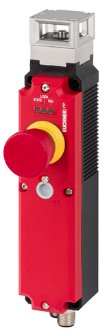
Safety switch without guard locking CTP-AP EXTENDED, RFID, plug connector M12, EMERGENCY STOP, for connection to decentralized peripheral systems
- Extended (EMERGENCY STOP)
- Unicode
- 2 x plug connector(s) M12, 5-pin
- for connection to decentralized peripheral systems
Açıklama
Version Extended
The Extended version includes additional control and display elements.
Direct connection to decentralized peripheral systems
The connection via M12 plug connector(s) is optimized for direct connection to IP67 IO modules, such as ET200pro and ET200eco from SIEMENS, MVK from MURR and EP1957 from BECKHOFF.
Approach direction
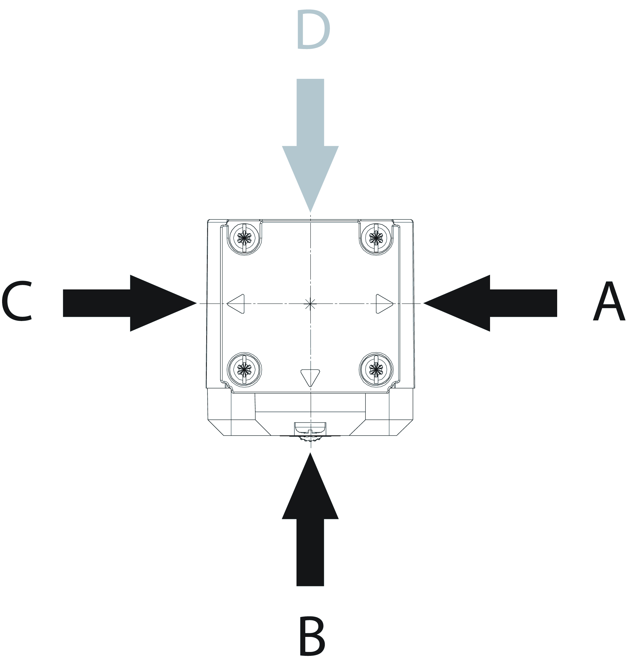
Horizontal
Can be adjusted in 90° steps
Unicode evaluation
Each actuator is highly coded (unicode). The switch detects only taught-in actuators. Additional actuators can be taught-in.
Only the last actuator taught-in is detected.
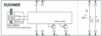
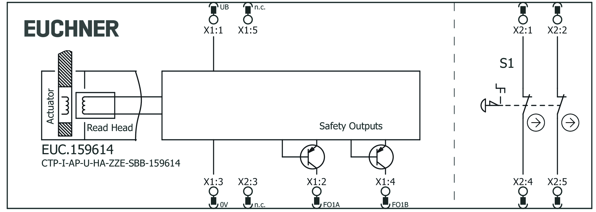
Terminal assignment
| Plug connector (view of connection side) | Pin | Designation | Function | Connecting cable conductor coloring |
|---|---|---|---|---|
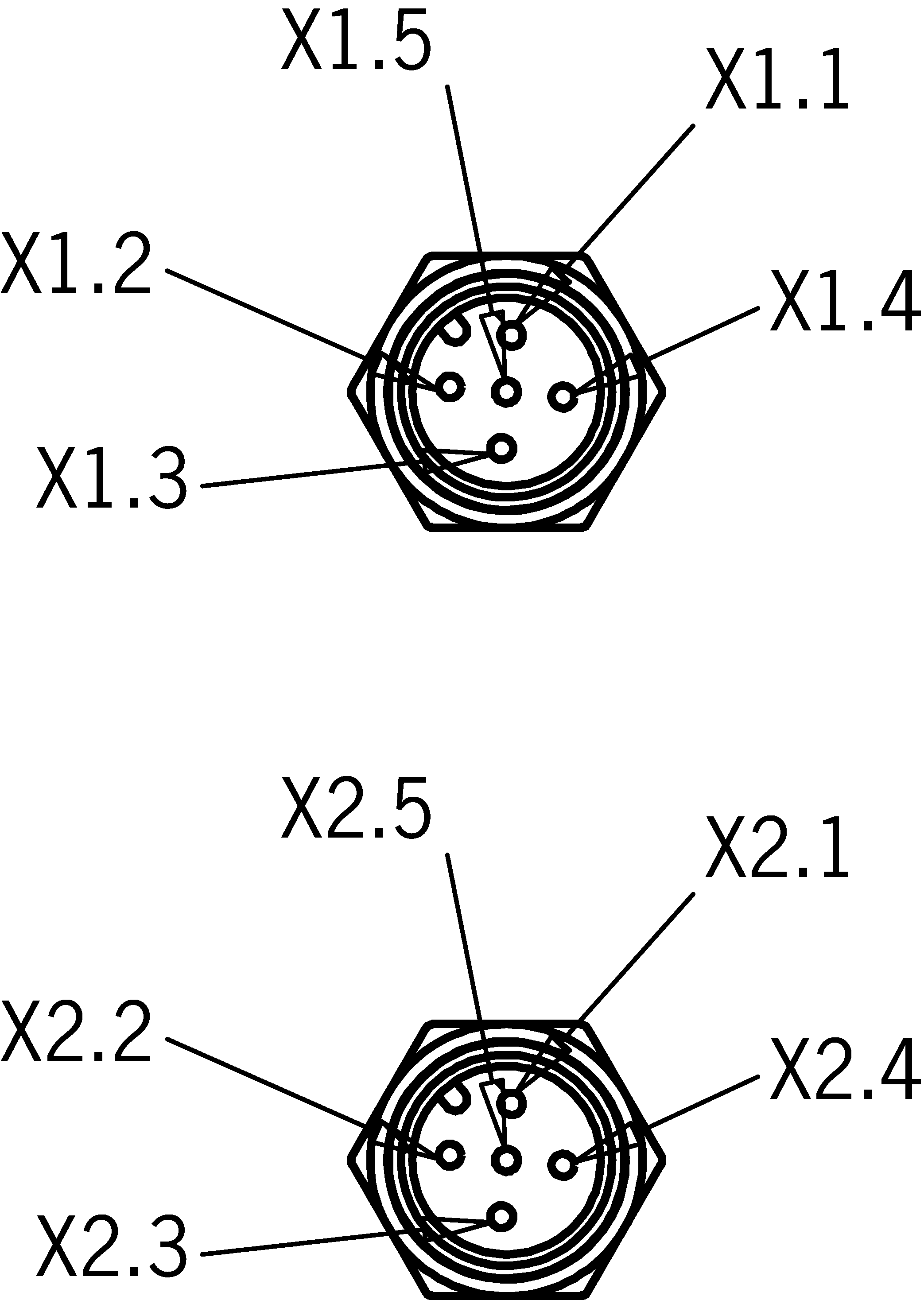 | X 1.1 | UB | Electronics operating voltage, 24 V DC | BN |
| X 1.2 | FO1A | Safety outputs channel A  | WH | |
| X 1.3 | 0 V UB | Electronics operating voltage, 0 V DC | BU | |
| X 1.4 | FO1B | Safety outputs channel B | BK | |
| X 1.5 | - | n.c. | GY | |
| X 2.1 | S1.A1 | EMERGENCY STOP (channel A contact 1) | BN | |
| X 2.2 | S1.B1 | EMERGENCY STOP (channel B contact 1) | WH | |
| X 2.3 | - | n.c. | BU | |
| X 2.4 | S1.A2 | EMERGENCY STOP (channel A contact 2) | BK | |
| X 2.5 | S1.B2 | EMERGENCY STOP (channel B contact 2) | GY |
Accessories required
Actuator is not included.
The safety switch can only be actuated in conjunction with the actuators provided for this purpose.
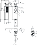
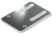
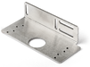
Dimensional drawings
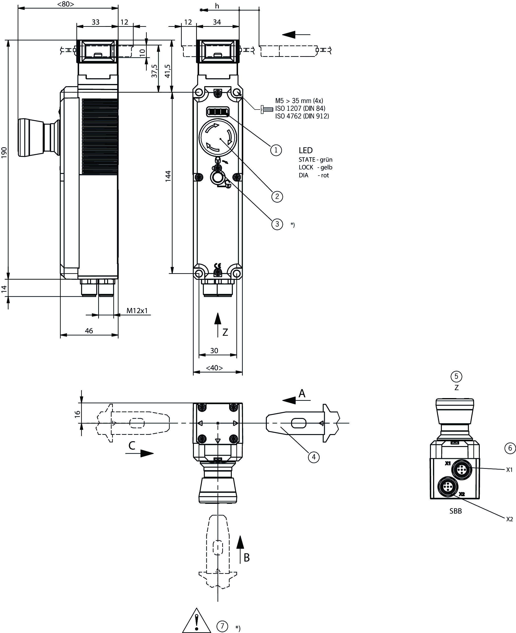
| 1 | LEDs: STATE green; LOCK yellow; DIA red |
| 2 | EMERGENCY STOP |
| 3 | Auxiliary release has no basic-position function *) |
| 4 | Order actuator separately |
| 5 | View Z |
| 6 | Plug connector aligned X1 M12, 5-pin; plug connector aligned X2 M12, 5-pin |
| 7 | Safety switch without auxiliary release *) Auxiliary release without function |
Connection examples
Teknik Veriler
Approvals


Workspace
| Repeat accuracy R | 10 % |
Operating and display elements
| Item | Color | Extras | Note slide-in label | Version | Slide-in label | Switching element | Number | Designation1 | LED |
|---|---|---|---|---|---|---|---|---|---|
| 1 | Emergency stop | 2 PD |
Electrical connection values
| Fuse | |
| external (operating voltage UB) | 0.25 ... 8 A |
| Power consumption | 1 W |
| Rated insulation voltage Ui | 50 V |
| Rated impulse voltage Uimp | 0.5 kV |
| Operating voltage DC | |
| UUB | 24 V DC -15% ... +15% reverse polarity protected, regulated, residual ripple<5%, PELV |
| EMC protection requirements | Acc. to EN IEC 60947-5-3 |
| Utilization category | |
| DC-13 | 24V 150mA (Caution: outputs must be protected with a free-wheeling diode in case of inductive loads) |
| Switching load | |
| according to UL | 24V DC, Class 2 (alternatively, see operating instructions) |
| Safety class | III |
| Current consumption | |
| IUB | 40 mA |
| Test pulse duration | max. 0.3 ms (Applies to a load with C<= 30nF and R<= 20kOhm) |
| Test pulse interval | min. 100 ms |
| Degree of contamination (external, according to EN 60947-1) | 3 |
| Emergency stop | |
| Breaking capacity | max. 0.25 W |
| Switching voltage | 5 ... 24 V |
| Switching current | 1 ... 100 mA |
| Safety outputs FO1A/FO1B | |
| Output type | 2 semiconductor outputs, p-switching, short circuit-proof |
| Output voltage | |
| LOW U(FO1A) / U(FO1B) | 0 ... 1 V DC |
| HIGH U(FO1A) / U(FO1B) | UB-1.5 ... UB V DC |
| Discrepancy time | |
| both safety outputs | max. 10 ms Acc. to EN IEC 60947-5-3 |
| Turn-on time | max. 400 ms |
| Off-state current Ir | max. 0.25 mA |
| Switching current | |
| per safety output FO1A / FO1B | 1 ... 150 mA |
Mechanical values and environment
| Anfahrgeschwindigkeit | max. 20 m/min |
| Connection type | 2 plug connector M12, 5-pin |
| Extraction force | 20 N |
| Ready delay | max. 1 s |
| Actuating force | 10 N |
| Installation orientation | any |
| Switching frequency | max. 0.5 Hz |
| Storage temperature | -25 ... 70 °C |
| Mechanical life | 1 x 10⁶ |
| Overtravel | 5 mm |
| Shock and vibration resistance | Acc. to EN IEC 60947-5-3 |
| Degree of protection | IP65 (In the inserted and screwed tight state) |
| Ambient temperature | |
| at UB = 24 V DC | -20 ... 55 °C |
| Material | |
| Switch head cover | Die-cast zinc |
| Safety switch housing | Reinforced thermoplastic |
Characteristic values according to EN ISO 13849-1 and EN IEC 62061
| Mission time | 20 y |
| Category | 4 |
| Performance Level | PL e |
| PFHD | 4.1 x 10 -9 |
Characteristic values according to EN ISO 13849-1 and EN IEC 62061
| PL | Maximum SIL | PFHD | Category | Mission time | |
|---|---|---|---|---|---|
| Monitoring of the guard position | PL e | - | 4.1x10⁻⁹ | 4 | 20 y |
| B10D | Mission time | |
|---|---|---|
| Emergency stop | 0.13x10⁶ | 20 y |
Miscellaneous
| Notices for UL approval | Operation only with UL Class 2 power supply or equivalent measures; see operating instructions |
| Detent mechanism | Snap-in bolt |
Aksesuar
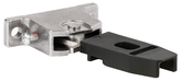
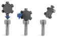
Actuator
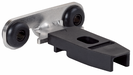

Hinged actuator for safety switch CTP/CTA


122671
A-C-H-RL-LS-122671
A-C-H-RL-LS-122671
- Hinged actuator for doors hinged on the left
- Two safety screws included
122675
A-C-H-RO-LS-122675
A-C-H-RO-LS-122675
- Hinged actuator for top-hinged doors
- Two safety screws included
122672
A-C-H-RR-LS-122672
A-C-H-RR-LS-122672
- Hinged actuator for doors hinged on the right
- Two safety screws included
122676
A-C-H-RU-LS-122676
A-C-H-RU-LS-122676
- Hinged actuator for bottom-hinged doors
- Two safety screws included
Connection material
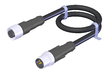
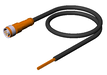
Connecting cable with 2 plug connectors M12, 5-pin, 1.5 m, AIDA standard


159356
C-M12F05-05X034PU01,5-M12M05-159356
C-M12F05-05X034PU01,5-M12M05-159356
- M12 female plug to M12 plug connector, 5-pin
- Straight female plug and plug connector
- Connecting cable according to AIDA standard
- PUR cable, sheath color gray
- Cable length 1.5 m
159363
C-M12F05-05X034PU01,5-M12M05-159363
C-M12F05-05X034PU01,5-M12M05-159363
- M12 female plug to M12 plug connector, 5-pin
- Straight female plug and plug connector
- Connecting cable according to AIDA standard
- PUR cable, sheath color yellow
- Cable length 1.5 m
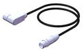
Connecting cable with 2 plug connectors M12, 5-pin, 10 m
119947
C-M12F05-05X034PU10,0-M12M05-119947
C-M12F05-05X034PU10,0-M12M05-119947
- M12 female plug to M12 plug connector, 5-pin
- Straight female plug and plug connector
- PUR cable
- Cable length 10 m
100181
C-M12F05-05X034PV10,0-M12M05-100181
C-M12F05-05X034PV10,0-M12M05-100181
- M12 female plug to M12 plug connector, 5-pin
- Straight female plug and plug connector
- PVC cable
- Cable length 10 m
Connecting cable with 2 plug connectors M12, 5-pin, 10 m, AIDA standard
159360
C-M12F05-05X034PU10,0-M12M05-159360
C-M12F05-05X034PU10,0-M12M05-159360
- M12 female plug to M12 plug connector, 5-pin
- Straight female plug and plug connector
- Connecting cable according to AIDA standard
- PUR cable, sheath color gray
- Cable length 10 m
159920
C-M12F05-05X034PU10,0-M12M05-159920
C-M12F05-05X034PU10,0-M12M05-159920
- M12 female plug to M12 plug connector, 5-pin
- Straight female plug and plug connector
- Connecting cable according to AIDA standard
- PUR cable, sheath color yellow
- Cable length 10 m
Connecting cable with 2 plug connectors M12, 5-pin, 15 m, AIDA standard
159361
C-M12F05-05X034PU15,0-M12M05-159361
C-M12F05-05X034PU15,0-M12M05-159361
- M12 female plug to M12 plug connector, 5-pin
- Straight female plug and plug connector
- Connecting cable according to AIDA standard
- PUR cable, sheath color gray
- Cable length 15 m
159921
C-M12F05-05X034PU15,0-M12M05-159921
C-M12F05-05X034PU15,0-M12M05-159921
- M12 female plug to M12 plug connector, 5-pin
- Straight female plug and plug connector
- Connecting cable according to AIDA standard
- PUR cable, sheath color yellow
- Cable length 15 m
Connecting cable with 2 plug connectors M12, 5-pin, 1 m, AIDA standard
159355
C-M12F05-05X034PU01,0-M12M05-159355
C-M12F05-05X034PU01,0-M12M05-159355
- M12 female plug to M12 plug connector, 5-pin
- Straight female plug and plug connector
- Connecting cable according to AIDA standard
- PUR cable, sheath color gray
- Cable length 1 m
159362
C-M12F05-05X034PU01,0-M12M05-159362
C-M12F05-05X034PU01,0-M12M05-159362
- M12 female plug to M12 plug connector, 5-pin
- Straight female plug and plug connector
- Connecting cable according to AIDA standard
- PUR cable, sheath color yellow
- Cable length 1 m
Connecting cable with 2 plug connectors M12, 5-pin, 20 m
119971
C-M12F05-05X034PU20,0-M12M05-119971
C-M12F05-05X034PU20,0-M12M05-119971
- M12 female plug to M12 plug connector, 5-pin
- Straight female plug and plug connector
- PUR cable
- Cable length 20 m
100182
C-M12F05-05X034PV20,0-M12M05-100182
C-M12F05-05X034PV20,0-M12M05-100182
- M12 female plug to M12 plug connector, 5-pin
- Straight female plug and plug connector
- PVC cable
- Cable length 20 m
Connecting cable with 2 plug connectors M12, 5-pin, 3 m, AIDA standard
159357
C-M12F05-05X034PU03,0-M12M05-159357
C-M12F05-05X034PU03,0-M12M05-159357
- M12 female plug to M12 plug connector, 5-pin
- Straight female plug and plug connector
- Connecting cable according to AIDA standard
- PUR cable, sheath color gray
- Cable length 3 m
159364
C-M12F05-05X034PU03,0-M12M05-159364
C-M12F05-05X034PU03,0-M12M05-159364
- M12 female plug to M12 plug connector, 5-pin
- Straight female plug and plug connector
- Connecting cable according to AIDA standard
- PUR cable, sheath color yellow
- Cable length 3 m
Connecting cable with 2 plug connectors M12, 5-pin, 5 m
119932
C-M12F05-05X034PU05,0-M12M05-119932
C-M12F05-05X034PU05,0-M12M05-119932
- M12 female plug to M12 plug connector, 5-pin
- Straight female plug and plug connector
- PUR cable
- Cable length 5 m
100180
C-M12F05-05X034PV05,0-M12M05-100180
C-M12F05-05X034PV05,0-M12M05-100180
- M12 female plug to M12 plug connector, 5-pin
- Straight female plug and plug connector
- PVC cable
- Cable length 5 m
Connecting cable with 2 plug connectors M12, 5-pin, 5 m, AIDA standard
159358
C-M12F05-05X034PU05,0-M12M05-159358
C-M12F05-05X034PU05,0-M12M05-159358
- M12 female plug to M12 plug connector, 5-pin
- Straight female plug and plug connector
- Connecting cable according to AIDA standard
- PUR cable, sheath color gray
- Cable length 5 m
159365
C-M12F05-05X034PU05,0-M12M05-159365
C-M12F05-05X034PU05,0-M12M05-159365
- M12 female plug to M12 plug connector, 5-pin
- Straight female plug and plug connector
- Connecting cable according to AIDA standard
- PUR cable, sheath color yellow
- Cable length 5 m
Connecting cable with 2 plug connectors M12, 5-pin, 8 m, AIDA standard
159359
C-M12F05-05X034PU08,0-M12M05-159359
C-M12F05-05X034PU08,0-M12M05-159359
- M12 female plug to M12 plug connector, 5-pin
- Straight female plug and plug connector
- Connecting cable according to AIDA standard
- PUR cable, sheath color gray
- Cable length 8 m
159919
C-M12F05-05X034PU08,0-M12M05-159919
C-M12F05-05X034PU08,0-M12M05-159919
- M12 female plug to M12 plug connector, 5-pin
- Straight female plug and plug connector
- Connecting cable according to AIDA standard
- PUR cable, sheath color yellow
- Cable length 8 m
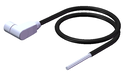
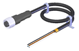
M12 extension PUR, 5-pin, plug connectors at both ends, 10 m
115565
C-M12F05-05X025PU10,0-M12M05-115565
C-M12F05-05X025PU10,0-M12M05-115565
- M12 female plug, 5-pin (angled) to M12 plug connector (straight)
- plug connectors at both ends
- PUR cable
- Cable length 10 m
- with cable exit A (right)
115566
C-M12F05-05X025PU10,0-M12M05-115566
C-M12F05-05X025PU10,0-M12M05-115566
- M12 female plug, 5-pin (angled) to M12 plug connector (straight)
- plug connectors at both ends
- PUR cable
- Cable length 10 m
- with cable exit C (left)

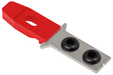
Metal bolt


Bolt for safety switch CTP, CTA

123653
RIEGEL CTP-AC-123653
RIEGEL CTP-AC-123653
- Steel bolt
- For doors hinged on the right and left
- Can be locked in open position with padlocks
- Actuator included
137354
RIEGEL CTP-AC-C2308-137354
RIEGEL CTP-AC-C2308-137354
- Steel bolt
- For doors hinged on the right and left
- Can be locked in open position with padlocks
- Actuator included
- Bolt without door stop, suitable for swing doors
Mounting accessories
Efficient protection against tampering for safety switch mounting
161344
AM-C-SW4-V3-161344
AM-C-SW4-V3-161344
- Plastic inserts for hexagon socket screws a/f 4
- Efficient protection against tampering for safety switch mounting
- The packaging includes inserts for 18 screws
161348
AM-C-SW5-V3-161348
AM-C-SW5-V3-161348
- Plastic inserts for hexagon socket screws a/f 5
- Efficient protection against tampering for safety switch mounting
- The packaging includes inserts for 18 screws

İndirme
Komple paket
Tüm önemli belgeleri tek bir tıklama ile indirin.
İçerik:
- Kullanım talimatları ve kullanım talimatlarına veya kısa talimatlara yapılan tüm eklemeler
- Kullanım talimatlarını tamamlayan tüm veri sayfaları
- Uygunluk beyanı
Paketin tamamını indirin (ZIP, 7,1 MB)
Tek Belgeler
Declarations of conformity
EU-Konformitätserklärung

Dok. No.
Versiyon
Dil
Boyut
EU-Konformitätserklärung
Dok. No.
EDC2123042
Versiyon
Dil
Boyut
0,2 MB
UKCA-Konformitätserklärung

Dok. No.
Versiyon
Dil
Boyut
UKCA-Konformitätserklärung
Dok. No.
EDC20001501
Versiyon
Dil
Boyut
0,1 MB
Instructions
Operating Instructions Transponder-Coded Safety Switch Without Guard Locking CTP-I-AP Unicode/Multicode


Dok. No.
Versiyon
Dil
Boyut
Operating Instructions Transponder-Coded Safety Switch Without Guard Locking CTP-I-AP Unicode/Multicode
Dok. No.
2137526
Versiyon
02/21
Dil
Boyut
2,1 MB
Mode d’emploi Interrupteur de sécurité à codage par transpondeur sans interverrouillage CTP-I-AP Uni-/multicode
Dok. No.
2137526
Versiyon
02/21
Dil
Boyut
2,1 MB
Manual de instrucciones Interruptor de seguridad con codificación por transponder sin bloqueo CTP-I-AP Unicode/Multicode
Dok. No.
2137526
Versiyon
02/21
Dil
Boyut
2,1 MB
Betriebsanleitung Transpondercodierter Sicherheitsschalter ohne Zuhaltung CTP-I-AP Uni-/Multicode
Dok. No.
2137526
Versiyon
02/21
Dil
Boyut
2,1 MB
Istruzioni di impiego Finecorsa di sicurezza con codifica a transponder senza meccanismo di ritenuta CTP-I-AP Unicode/Multicode
Dok. No.
2137526
Versiyon
02/21
Dil
Boyut
2,1 MB
操作説明書 トランスポンダー コーデッド安全スイッチ ガードロックなし CTP-I-AP ユニコード/マルチコード
Dok. No.
2137526
Versiyon
02/21
Dil
Boyut
2,5 MB

Diğer Belgeler
Approvals and certificates
FCC

Dok. No.
Versiyon
Dil
Boyut
FCC
Dok. No.
Versiyon
Dil
Boyut
0,1 MB
UQS CTP-AP-AR_MGBS-AP-AR_
Dok. No.
Versiyon
Dil
Boyut
UQS CTP-AP-AR_MGBS-AP-AR_
Dok. No.
ECO2123565
Versiyon
Dil
Boyut
0,2 MB
WEEE

Dok. No.
Versiyon
Dil
Boyut
WEEE
Dok. No.
ECO20001806
Versiyon
Dil
Boyut
0,1 MB
c UL us

Dok. No.
Versiyon
Dil
Boyut
c UL us
Dok. No.
Versiyon
Dil
Boyut
0,3 MB
Sales documents


CAD Verileri

Sipariş verileri
| Sip. No. | 159614 |
| Makale adı | CTP-I-AP-U-HA-ZZE-SBB-159614 |
| Ağırlık | 0,56kg |
| Gümrük sınıfı | 85365019000 |
| ECLASS | 27-27-24-05 Safety-related transponder switch with guardlocking |