CES-A-ABA-01 (Order no. 071850)
Choose content
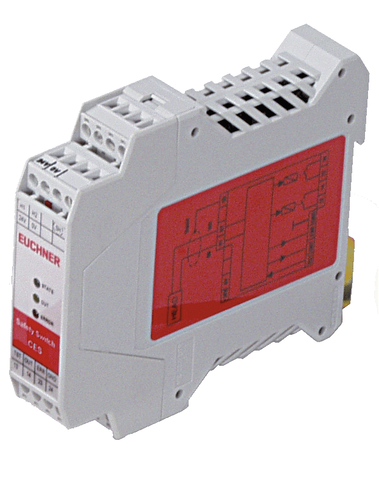
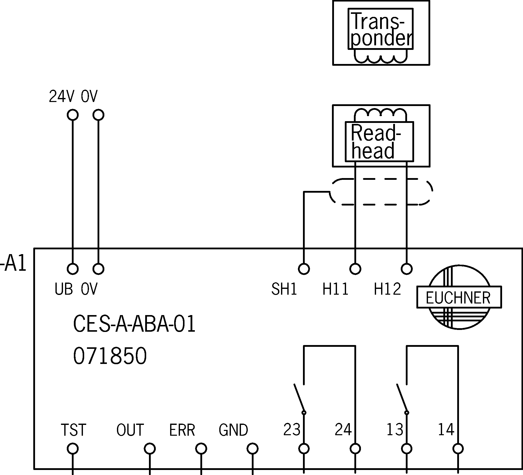
Evaluation unit CES-A-ABA-01 (for 1 read head)
- 1 read head can be connected
- 2 safety contacts (relay contacts)
- 1 internal normally open contact per safety contact
- Unicode evaluation unit
- Category 3 / PL e according to EN ISO 13849-1
Description
Unicode evaluation unit
Each actuator is highly coded (unicode). The evaluation unit detects only actuators that have been taught-in. Max. 8 actuators can be taught-in.
Only the last actuator taught-in is detected.
Category according to EN ISO 13849-1
Due to two redundant relay outputs (safety outputs) with internally monitored contacts, suitable for:
- Category 3 / PL e according to EN ISO 13849-1
To achieve the stated category, both safety contacts must always be evaluated.
Actuating range
The evaluation unit enables a reduced actuating range.
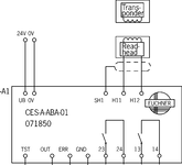
TST | Input for self-test |
OUT | Monitoring output (semiconductor) |
ERR | Diagnostic output |
GND | Connected internally to 0V (not for high currents) |
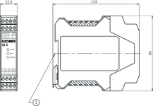
Dimensional drawings
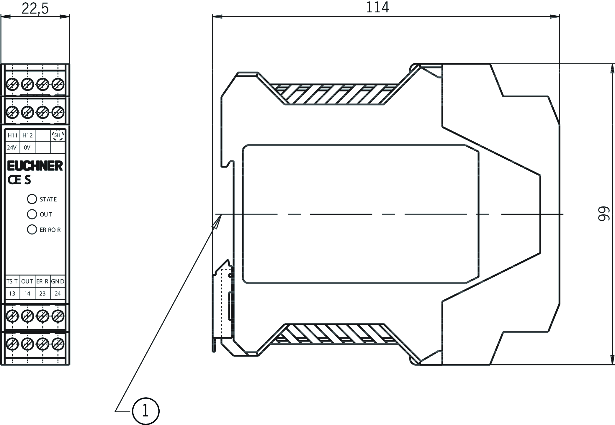
| 1 | Suitable for 35 mm mounting rail according to EN 60715 |
Connection examples
Technical data
Approvals


Workspace
| Repeat accuracy R | |
| according to EN 60947-5-2 | 10 % |
Operating and display elements
| LED display | |
| Status LED | |
| Diagnostics LED | |
| Safety contacts status |
Electrical connection values
| Fuse | |
| external (operating voltage UB) | 0.25 ... 8 A |
| Connection cross section | |
| Screw terminals | 0.25 ... 2.5 mm² |
| Rated insulation voltage Ui | 63 V |
| Rated impulse voltage Uimp | 1.5 kV |
| Operating voltage DC | |
| UB | 21 ... 24 ... 27 V DC regulated, residual ripple<5% |
| EMC protection requirements | Acc. to EN IEC 60947-5-3 |
| Current consumption | |
| (with relay energized) | 150 mA (without taking into account the load currents at the monitoring outputs) |
| Degree of contamination (external, according to EN 60947-1) | 2 |
| Input: test input TST | |
| Input voltage | |
| LOW | 0 ... 2 V DC |
| HIGH | 15 ... UB V DC |
| Monitoring outputs: diagnostics ERR, door monitoring output OUT | |
| Output type | Semiconductor output, p-switching, not short circuit-proof |
| Output voltage | 0.8 x UB ... UB V DC |
| Output current | max. 20 mA |
| Safety contacts 13/14, 23/24 | |
| Fuse | |
| external (safety circuit) according to EN 60269-1 | 6 AgG or 6 A circuit breaker (characteristic B or C) |
| Output type | Relay contacts, floating |
| rated conditional short-circuit current | 100 A |
| Discrepancy time | |
| (between the operating points of both relays) | max. 120 ms |
| Utilization category | |
| DC-13 | 24V 3A |
| AC-12 | 60V 0.3A |
| DC-12 | 30V 6A |
| AC-12 | 30V 6A |
| DC-14 | 30V 2A |
| DC-12 | 60V 0.3A |
| Switching load | |
| according to c UL us | Class 2 max. 30 V AC / Class 2 max. 60 V DC |
| Switching current | |
| at switching voltage AC/DC 10 ... 30 V | 10 ... 6000 mA |
| at switching voltage AC/DC 21 ... 60 V | 1 ... 300 mA |
Mechanical values and environment
| Connection type | plug-in screw terminals, coded |
| Number of read heads | 1 read head can be connected |
| Ready delay | max. 3 s (After the operating voltage is switched on, the relay outputs are switched off and the door monitoring output is set to LOW level during the ready delay.) |
| Switching frequency | max. 1 Hz (If the current load is>100 mA, a switching frequency of 0.1 Hz should not be exceeded as this will affect the mechanical life of the relay contacts.) |
| Storage temperature | -25 ... 70 °C |
| Atmospheric humidity | |
| not condensing | max. 80 % rH |
| Mounting distance | |
| between evaluation units | min. 10 mm |
| Mounting type | Mounting rail TH 35 (EN IEC 60715) |
| Response time | |
| after change in the actuation status | max. 180 ms (Corresponds to the risk time according to EN 60947-5-3. This is the maximum OFF time for the safety outputs following removal of an actuator.) |
| Degree of protection | IP20 |
| Ambient temperature | |
| at UB = 24 V DC | -20 ... 55 °C |
| Dwell time | min. 0.5 s (The dwell time of an actuator inside and outside the actuating range must be at least 0.5 s to ensure safe detection of internal faults in the evaluation unit (self-monitoring).) |
| Material | |
| Housing | Plastic PA6.6 |
| Safety contacts 13/14, 23/24 | |
| Number of safety contacts | 2 Relay with internally monitored contacts (to ensure safety, both safety outputs (13/14 and 23/24) must always be evaluated) |
| Mechanical life | |
| Operating cycles (relay) | 10 x 10⁶ |
Characteristic values according to EN ISO 13849-1 and EN IEC 62061
| PL | Maximum SIL | PFHD | Category | Mission time | ||
|---|---|---|---|---|---|---|
| Monitoring of the guard position | Read head CES-A-L.. | PL e | - | 4.3x10⁻⁸ | 3 | 20 y |
| Only applies for switching voltage 24V DC and switching current up to 0.1 A (max. switching cycles 760,000 1/y) OR up to 1 A (max. switching cycles 153,000 1/y ) OR up to 3 A (max. switching cycles 34,600 1/y) | ||||||
Miscellaneous
| Notices for UL approval | Operation only with UL Class 2 power supply or equivalent measure. |
In combination with read head CES-A-LQA-SC
| Mounting distance | |
| between read heads | min. 80 mm |
In combination with read head CES-A-LQA-SC and actuator CES-A-BBA-071840, CES-A-BCA
| Switch-on distance | |
| for side approach direction (distance in x direction 3 mm) | +/- 21 mm (for surface mounting of the read head and the actuator) |
| with vertical approach direction (center offset m = 0) | 7.5 mm (for surface mounting of the read head and the actuator) |
| Secured switch-off distance sar | max. 30 mm |
| Secured switching distance sao | |
| for side approach direction (distance in x direction 3 mm) | min. +/- 18 mm (for surface mounting of the read head and the actuator) |
| with vertical approach direction (center offset m = 0) | min. 5 mm (for surface mounting of the read head and the actuator) |
| Switching hysteresis | |
| with vertical approach direction (center offset m = 0) | 1 ... 1.5 mm (for surface mounting of the read head and the actuator) |
| for side approach direction (distance in x direction 3 mm) | 1 ... 1.3 mm (for surface mounting of the read head and the actuator) |
In combination with read head CES-A-LQA-SC and actuator CES-A-BQA
| Switch-on distance | |
| for side approach direction (distance in x direction 5 mm) | +/- 21 mm (for surface mounting of the read head and the actuator) |
| with vertical approach direction (center offset m = 0) | 14 mm (for surface mounting of the read head and the actuator) |
| Secured switch-off distance sar | max. 45 mm |
| Secured switching distance sao | |
| for side approach direction (distance in x direction 5 mm) | min. +/- 18 mm (for surface mounting of the read head and the actuator) |
| with vertical approach direction (center offset m = 0) | min. 9 mm (for surface mounting of the read head and the actuator) |
| Switching hysteresis | |
| for side approach direction (distance in x direction 5 mm) | 0.5 ... 1.5 mm (for surface mounting of the read head and the actuator) |
| with vertical approach direction (center offset m = 0) | 1.3 ... 2 mm (for surface mounting of the read head and the actuator) |
In combination with read head CES-A-LNA-SC-077715, CES-A-LNA-05P-077806, CES-A-LNA-10P-077807, CES-A-LNA-05V-071845, CES-A-LNA-10V-071846, CES-A-LNA-15V-071847, CES-A-LNA-25V-071975, CES-A-LNA-15P-084682, CES-A-LCA-10V and actuator CES-A-BDA-20
| Actuator distance s | |
| Minimum distance for side approach direction | min. 1 mm |
| Switch-on distance | |
| with center offset m=0 | 3.3 mm (on flush mounting of the actuator in stainless steel) |
| with center offset m=0 | 7 mm (on mounting of the actuator in non-metallic environment) |
| with center offset m=0 | 4.4 mm (on surface mounting of the actuator on steel) |
| with center offset m=0 | 4 mm (on surface mounting of the actuator on stainless steel) |
| with center offset m=0 | 3.6 mm (on flush mounting of the actuator in steel) |
| Secured switch-off distance sar | max. 24 mm |
| Secured switching distance sao | |
| with center offset m=0 | min. 3.3 mm (on surface mounting of the actuator on stainless steel) |
| with center offset m=0 | min. 3.0 mm (on flush mounting of the actuator in steel) |
| with center offset m=0 | min. 3.6 mm (on surface mounting of the actuator on steel) |
| with center offset m=0 | min. 2.7 mm (on flush mounting of the actuator in stainless steel) |
| with center offset m=0 | min. 6 mm (on mounting of the actuator in non-metallic environment) |
| Switching hysteresis | |
| 0.4 ... 1.1 mm (on surface mounting of the actuator on stainless steel) | |
| 0.5 ... 1.5 mm (on mounting of the actuator in non-metallic environment) | |
| 0.4 ... 1.2 mm (on surface mounting of the actuator on steel) | |
| 0.3 ... 1.0 mm (on flush mounting of the actuator in steel) | |
| 0.3 ... 0.9 mm (on flush mounting of the actuator in stainless steel) |
In combination with read head CES-A-LNA-SC-077715, CES-A-LNA-05P-077806, CES-A-LNA-10P-077807, CES-A-LNA-05V-071845, CES-A-LNA-10V-071846, CES-A-LNA-15V-071847, CES-A-LNA-25V-071975, CES-A-LNA-15P-084682, CES-A-LCA-10V and actuator CES-A-BBA-071840, CES-A-BCA
| Switch-on distance | |
| with center offset m=0 | 6 mm (for flush mounting of the read head and actuator in aluminum) |
| Secured switch-off distance sar | max. 23 mm |
| Secured switching distance sao | |
| with center offset m=0 | min. 5 mm |
| Switching hysteresis | 0.5 ... 1.5 mm (for flush mounting of the read head and actuator in aluminum) |
In combination with read head CES-A-LMN-SC
| Mounting distance | |
| between read heads | min. 20 mm |
In combination with read head CES-A-LNA-SC-077715, CES-A-LNA-05P-077806, CES-A-LNA-10P-077807, CES-A-LNA-05V-071845, CES-A-LNA-10V-071846, CES-A-LNA-15V-071847, CES-A-LNA-25V-071975, CES-A-LNA-15P-084682, CES-A-LCA-10V
| Mounting distance | |
| between read heads | min. 50 mm |
In combination with read head CES-A-LMN-SC and actuator CES-A-BMB
| Switch-on distance | |
| with center offset m=0 | 2.5 mm (for surface mounting of the read head in steel) |
| Secured switch-off distance sar | max. 8.5 mm |
| Secured switching distance sao | |
| with center offset m=0 | min. 1.6 mm (for surface mounting of the read head in steel) |
| Switching hysteresis | 0.2 ... 0.3 mm (for surface mounting of the read head in steel) |
Accessories
CES read heads


Downloads
Complete package
Download all important documents with a single click.
Content:
- The operating instructions and any additions to the operating instructions or brief instructions
- Any data sheets to supplement the operating instructions
- The declaration of conformity
Download Complete Package (ZIP, 4,4 MB)
Single Documents
Declarations of conformity
EU-Konformitätserklärung

Doc. no.
Version
Language
Size
EU-Konformitätserklärung
Doc. no.
EDC2077154
Version
Language
Size
0,2 MB
UKCA-Konformitätserklärung

Doc. no.
Version
Language
Size
UKCA-Konformitätserklärung
Doc. no.
EDC20001581
Version
Language
Size
0,2 MB
Instructions
Operating Instructions Non-Contact Safety System CES-A-ABA-01/CES-A-ABA-01B (Unicode)


Doc. no.
Version
Language
Size
Operating Instructions Non-Contact Safety System CES-A-ABA-01/CES-A-ABA-01B (Unicode)
Doc. no.
2071873
Version
19-08/20
Language
Size
1,3 MB
Mode d'emploi Système de sécurité sans contact CES-A-ABA-01/CES-A-ABA-01B (unicode)
Doc. no.
2071873
Version
19-08/20
Language
Size
1,3 MB
Manual de instrucciones Sistema de seguridad sin contacto CES-A-ABA-01/CES-A-ABA-01B (Unicode)
Doc. no.
2071873
Version
19-08/20
Language
Size
1,3 MB
Betriebsanleitung Berührungsloses Sicherheitssystem CES-A-ABA-01/CES-A-ABA-01B (Unicode)
Doc. no.
2071873
Version
19-08/20
Language
Size
1,4 MB
Istruzioni di impiego Sistema di sicurezza senza contatto CES-A-ABA-01/CES-A-ABA-01B (Unicode)
Doc. no.
2071873
Version
19-08/20
Language
Size
1,3 MB

Other Documents
Approvals and certificates

S-Mark

Doc. no.
Version
Language
Size
S-Mark
Doc. no.
Version
Language
Size
0,8 MB
c UL us

Doc. no.
Version
Language
Size
c UL us
Doc. no.
Version
Language
Size
0,2 MB
CAD data

Ordering data
| Ordernumber | 071850 |
| Item designation | CES-A-ABA-01 |
| Gross weight | 0,245kg |
| Global Trade Item Number (GTIN) | 4047048000209 |
| Customs tariff number | 85364110 |
| ECLASS | 27-27-24-03 Safety-related transponder switch |
