CES-AH-C03-AH-SM-106300 (Order no. 106300)
Choose content
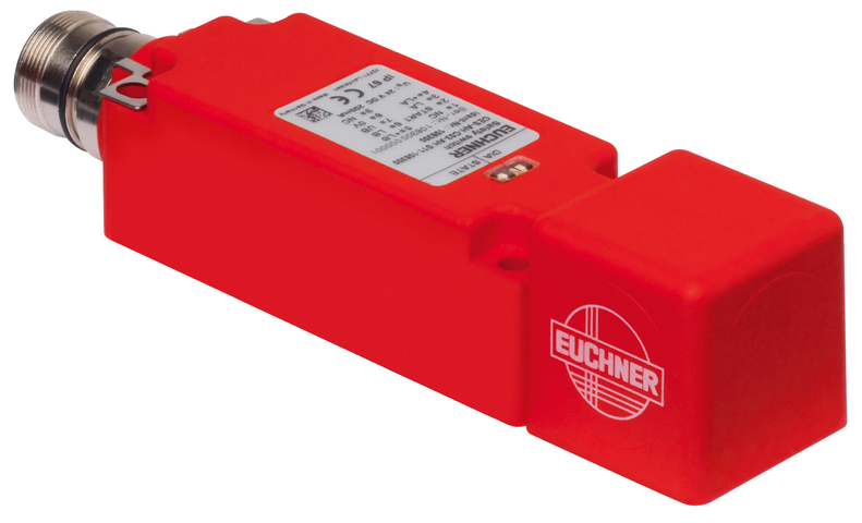
Non-contact safety switch CES-AH-C03-...
- Safety switch with integrated evaluation electronics
- Load currents of 3.5 A can be switched directly
- 2 safety outputs (semiconductor outputs)
- Category 3 / PL d according to EN ISO 13849-1
- With plug connector M23
- Approach direction A (not adjustable)
- Unicode
Description
Unicode evaluation
Each actuator is highly coded (unicode). The switch detects only taught-in actuators. Additional actuators can be taught-in.
Only the last actuator taught-in is detected.
Category according to EN ISO 13849-1
Due to two redundantly designed semiconductor outputs (safety outputs) with internal monitoring suitable for:
- Category 3 / PL d according to EN ISO 13849-1
Each safety path is independently safe.
LED indicator
STATE | Status LED |
DIA | Diagnostics LED |
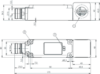
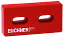
Dimensional drawings
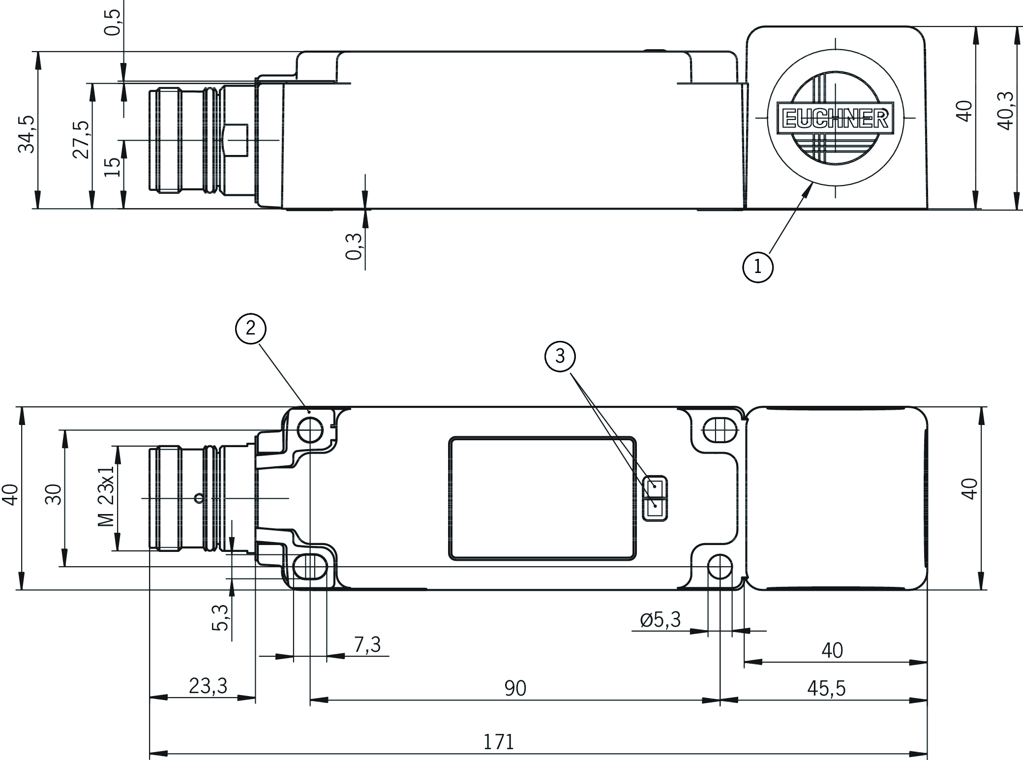
| 1 | Active face |
| 2 | shield spring |
| 3 | LED status indication |
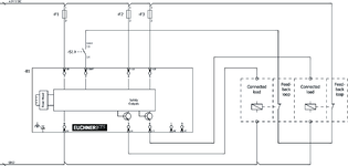
Connection examples
Connection examples
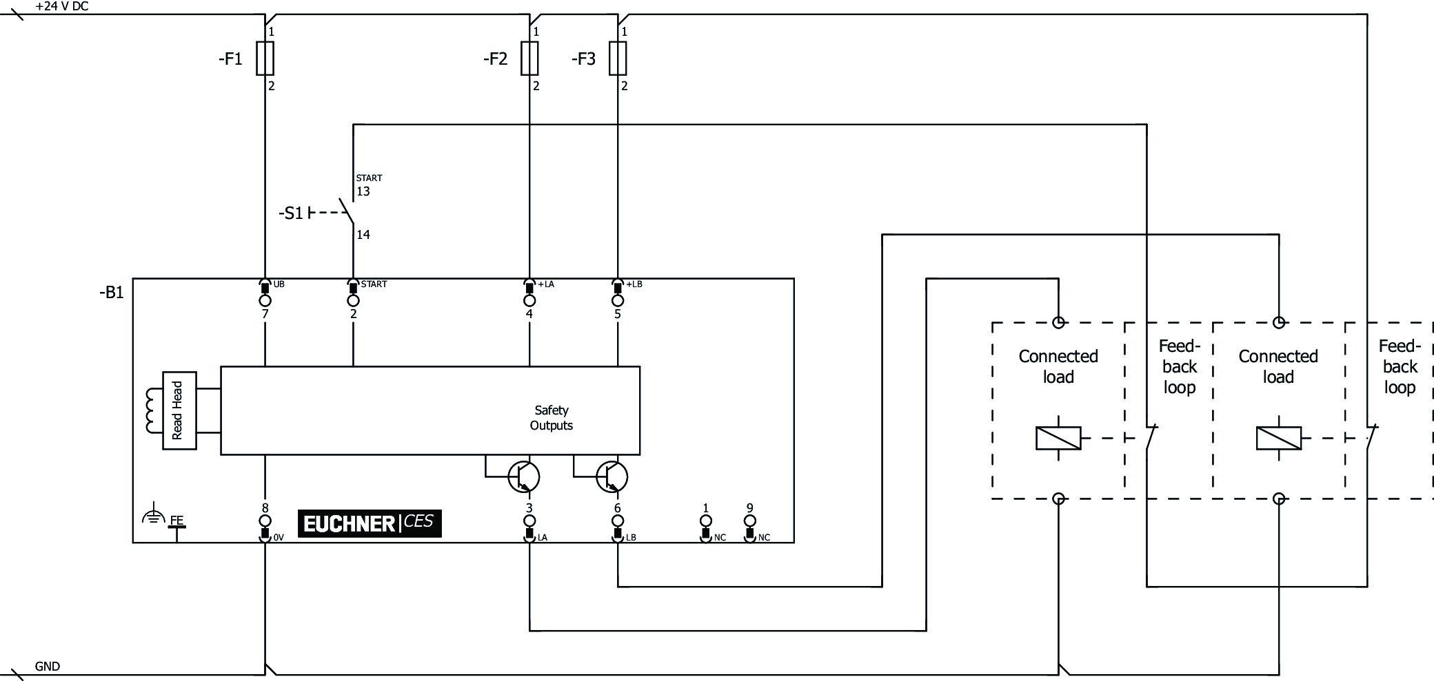
Connection examples
Technical data
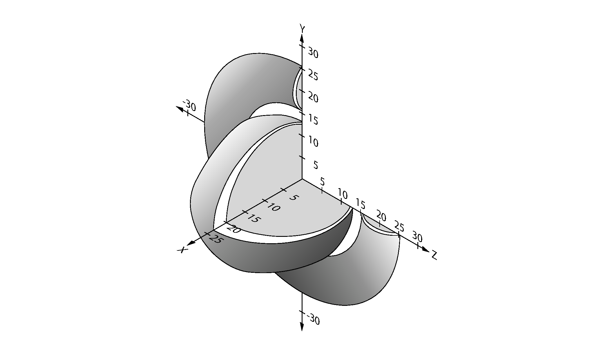
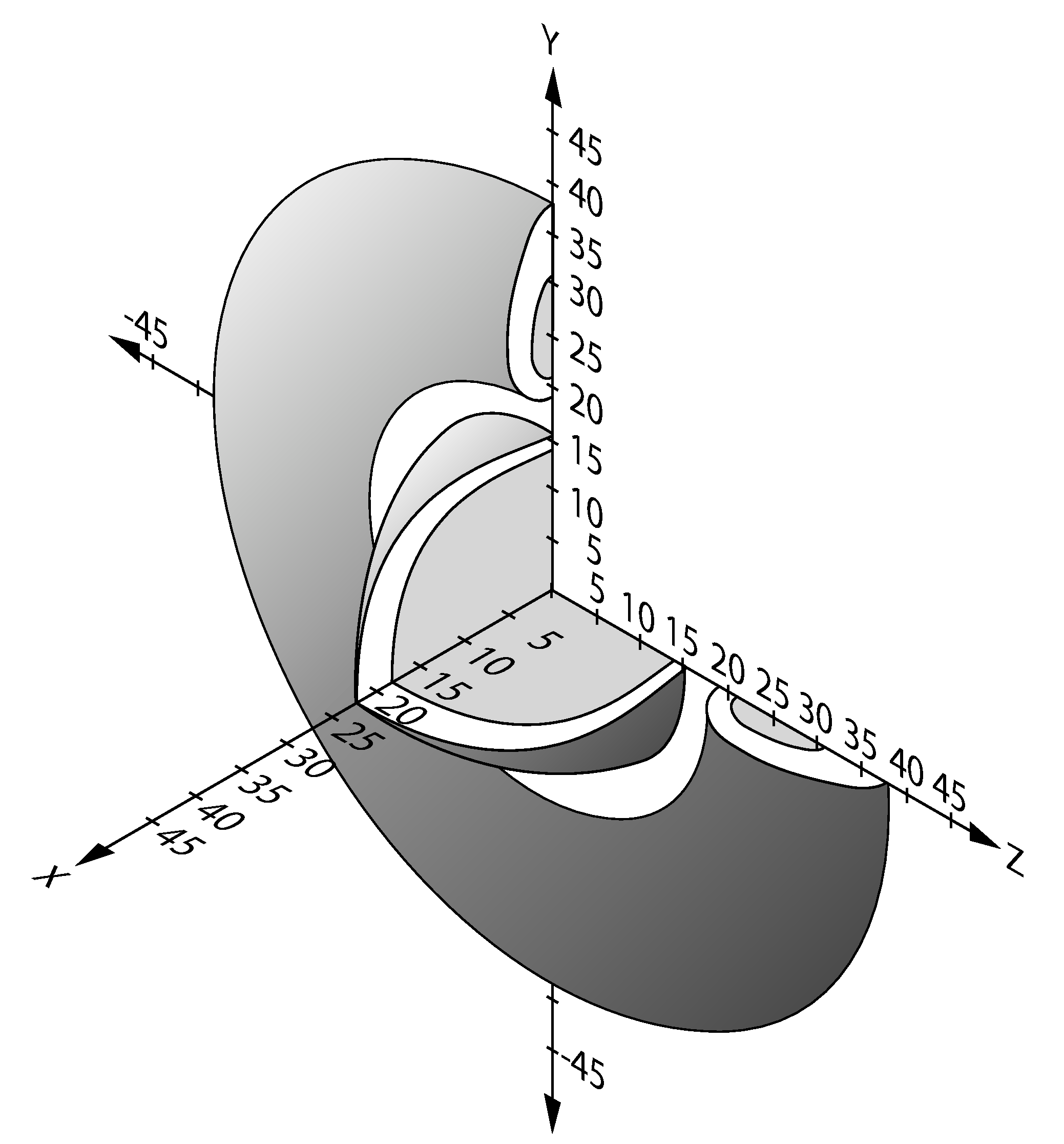
Workspace
| Repeat accuracy R | |
| according to EN 60947-5-2 | 10 % |
Operating and display elements
| LED display | 2 STATE (green) and DIA (red) |
Electrical connection values
| Fuse | |
| external (operating voltage, +LA and +LB) | 0.25 ... 10 A |
| Rated insulation voltage Ui | 75 V |
| Rated impulse voltage Uimp | 1.5 kV |
| Operating voltage DC | |
| UB | 20 ... 28 V DC reverse polarity protected, regulated, residual ripple<5%, PELV |
| Discrepancy time | max. 50 ms |
| Turn-on time | |
| Safety outputs LA / LB | max. 400 ms |
| EMC protection requirements | Acc. to EN IEC 60947-5-3 |
| Off-state current Ir | max. 0.5 mA |
| Risk time according to EN 60947-5-3 | max. 250 ms |
| Safety class | III |
| Current consumption | |
| no load on outputs | max. 150 mA |
| Degree of contamination (external, according to EN 60947-1) | 3 |
| Time delay | |
| In the fault state | 5 s (The switch remains in the fault state for this time before a reset is performed.) |
| Power supply outputs | |
| Power supply output load | |
| U(+LA)/U(+LB) | 20 ... 28 V DC (Power supply same UB, same GND potential.) |
| Safety output LA | |
| Output type | Semiconductor output, p-switching, short circuit-proof |
| Output voltage | |
| HIGH U(LA) | U(+LA) - 1.5 ... U(+LA) V DC (Values at a switching current of 3.5 A without taking into account the cable lengths.) |
| LOW U(LA) | 0 ... 4 V DC |
| rated conditional short-circuit current | 100 A |
| Utilization category | |
| DC-13 | 24V 3.5A (Caution: outputs must be protected with a free-wheeling diode in case of inductive loads.) |
| Switching current | 30 ... 3500 mA |
| Test pulse duration | max. 6 ms (With series connection, the value increases according to the number of switches used.) |
| Test pulse interval | min. 10000 ms |
| Safety output LB | |
| Output type | Semiconductor output, p-switching, short circuit-proof |
| Output voltage | |
| HIGH U(LB) | U(+LB) - 1.5 ... U(+LB) V DC (Values at a switching current of 3.5 A without taking into account the cable lengths.) |
| LOW U(LB) | 0 ... 4 V DC |
| rated conditional short-circuit current | 100 A |
| Utilization category | |
| DC-13 | 24V 3.5A (Caution: outputs must be protected with a free-wheeling diode in case of inductive loads.) |
| Switching current | 30 ... 3500 mA |
| Test pulse duration | max. 6 ms (With series connection, the value increases according to the number of switches used.) |
| Test pulse interval | min. 10000 ms |
| Start input | |
| Input voltage | |
| LOW | 0 ... 2 V DC |
| HIGH | 8 ... UB V DC |
Mechanical values and environment
| Dimensions | 40 x 40 x 171 |
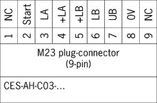
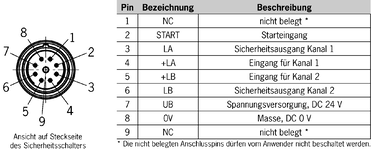
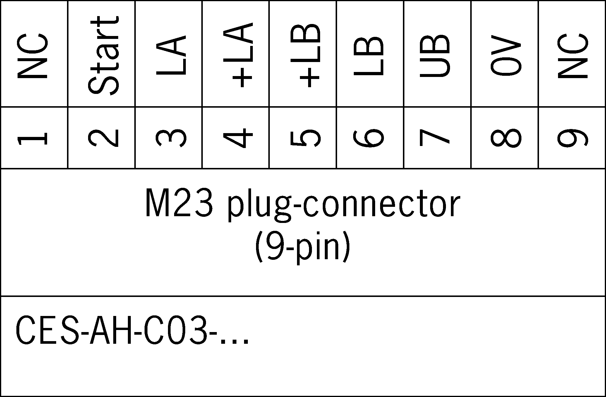
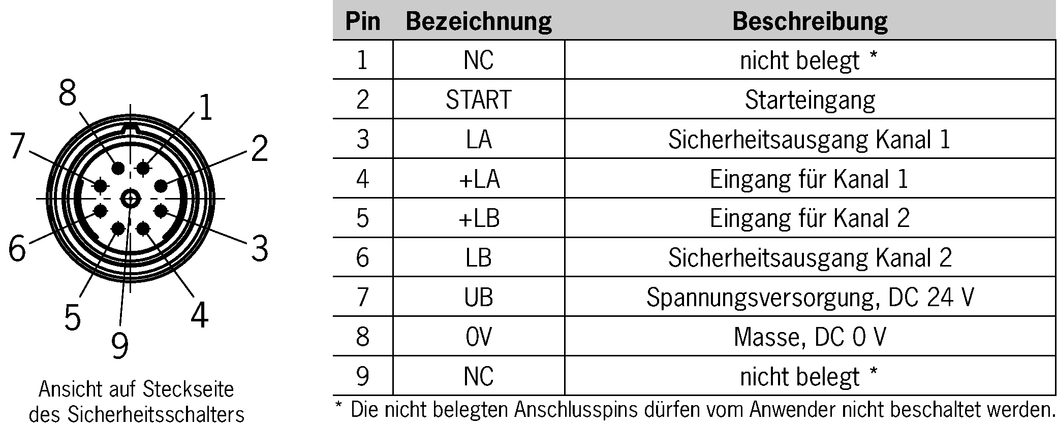
| Connection type | M23 plug connector, 9-pin |
| Tightening torque | |
| Fixing screws | max. 1 Nm |
| Ready delay | max. 3 s (After the operating voltage is switched on, the semiconductor outputs are switched off during the ready delay.) |
| Installation orientation | any |
| Switching frequency | max. 1 Hz |
| Mounting distance | |
| between switches | min. 80 mm |
| Shock and vibration resistance | Acc. to EN IEC 60947-5-3 |
| Degree of protection | IP67 |
| Ambient temperature | |
| at I(LA) / I(LB)>3 A | -20 ... 55 °C (+70 °C at I(LA) / I(LB)<3 A) |
| Dwell time | min. 0.5 s (The dwell time of an actuator inside and outside the actuating range must be at least 0.5 s to ensure safe detection of internal faults in the evaluation unit (self-monitoring).) |
| Material | |
| Housing | Plastic, PBT |
Characteristic values according to EN ISO 13849-1 and EN IEC 62061
| PL | Maximum SIL | PFHD | Category | Mission time | |
|---|---|---|---|---|---|
| Monitoring of the guard position | PL d | - | 1.03x10⁻⁷ | 3 | 20 y |
In combination with actuator CES-A-BPA-098775
| Actuator distance s | |
| Minimum distance for side approach direction | min. 6 mm (Minimum distance to prevent switching on in the side lobe of the read head.) |
| Switch-on distance | 22 mm (for surface mounting on aluminum; in a metal-free environment, the typical operating distance increases to 30 mm) |
| Secured switch-off distance sar | max. 58 mm |
| Secured switching distance sao | min. 18 mm |
| Switching hysteresis | 1 ... 2 mm |
In combination with actuator CES-A-BRN-100251
| Actuator distance s | |
| Minimum distance for side approach direction | min. 6 mm (Minimum distance to prevent switching on in the side lobe of the read head.) |
| Switch-on distance | 27 mm |
| Secured switch-off distance sar | max. 75 mm |
| Secured switching distance sao | min. 20 mm (The values apply to surface mounting of the actuator on steel.) |
| Switching hysteresis | 3 mm (The values apply to surface mounting of the actuator on steel.) |
In combination with actuator CES-A-BBA-071840, CES-A-BCA
| Actuator distance s | |
| Minimum distance for side approach direction | min. 4 mm (Minimum distance to prevent switching on in the side lobe of the read head.) |
| Switch-on distance | 20 mm |
| Secured switch-off distance sar | max. 40 mm |
| Secured switching distance sao | min. 18 mm (for surface mounting of the actuator) |
| Switching hysteresis | 2 ... 3 mm (for surface mounting of the actuator) |
Accessories


Downloads
Complete package
Download all important documents with a single click.
Content:
- The operating instructions and any additions to the operating instructions or brief instructions
- Any data sheets to supplement the operating instructions
- The declaration of conformity
Download Complete Package (ZIP, 2,3 MB)
Single Documents
Declarations of conformity


Other Documents
Sales documents
Flexibel sicher - Transpondercodierte Sicherheitssysteme CES

Doc. no.
Version
Language
Size
Flexibel sicher - Transpondercodierte Sicherheitssysteme CES
Doc. no.
119922
Version
06-06/22
Language
Size
8,4 MB


CAD data

Ordering data
| Ordernumber | 106300 |
| Item designation | CES-AH-C03-AH-SM-106300 |
| Gross weight | 0,45kg |
| Customs tariff number | 85365019000 |
| ECLASS | 27-27-24-03 Safety-related transponder switch |
