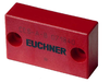
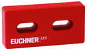
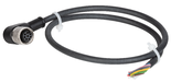
CES-AR-C01-AH-SA (Order no. 098941)
Non-contact safety switch CES-AR-C01...
- Safety switch with integrated evaluation electronics
- Up to 20 switches in series
- Short circuit monitoring
- 2 safety outputs (semiconductor outputs)
- Category 4 / PL e according to EN ISO 13849-1
- Unicode
Description
Approach direction
Can be adjusted in 90° steps
Short circuit monitoring
The switch generates its own clock signal on the output lines OA/OB. Pay attention to this aspect when connecting to control systems and relays.
Unicode evaluation
Each actuator is highly coded (unicode). The switch detects only taught-in actuators. Additional actuators can be taught-in.
Only the last actuator taught-in is detected.
Category according to EN 13849-1
Due to two redundantly designed semiconductor outputs (safety outputs) with internal monitoring suitable for:
- Category 4/PL e according to EN 13849-1
Important: To achieve the stated category in accordance with EN ISO 13849-1, both safety outputs (OA and OB) must be evaluated.
LED indicator
STATE | Status LED |
DIA | Diagnostics LED |
Additional connections
OUT | Monitoring output (semiconductor) |
RST | Reset input |
Typical operating distance
With actuators CES-A-BBA and CES-A-BCA
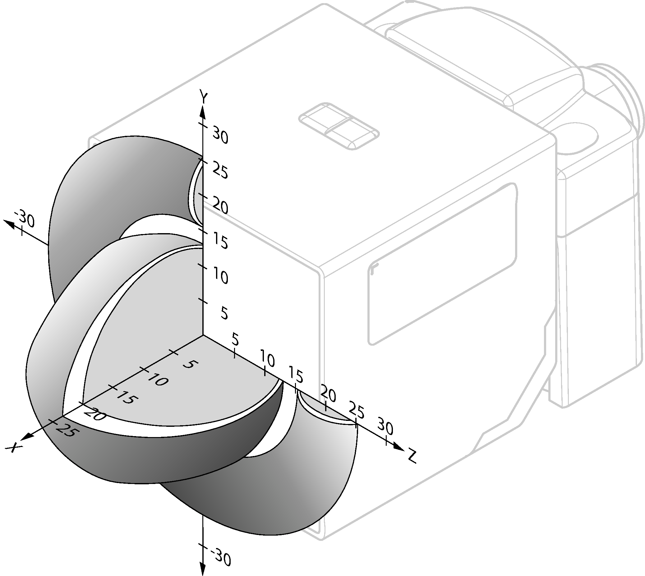
For a side approach direction for the actuator and safety switch, a minimum distance of s = 4 mm must be maintained so that the actuating range of the side lobes is not entered.
With actuator CES-A-BPA
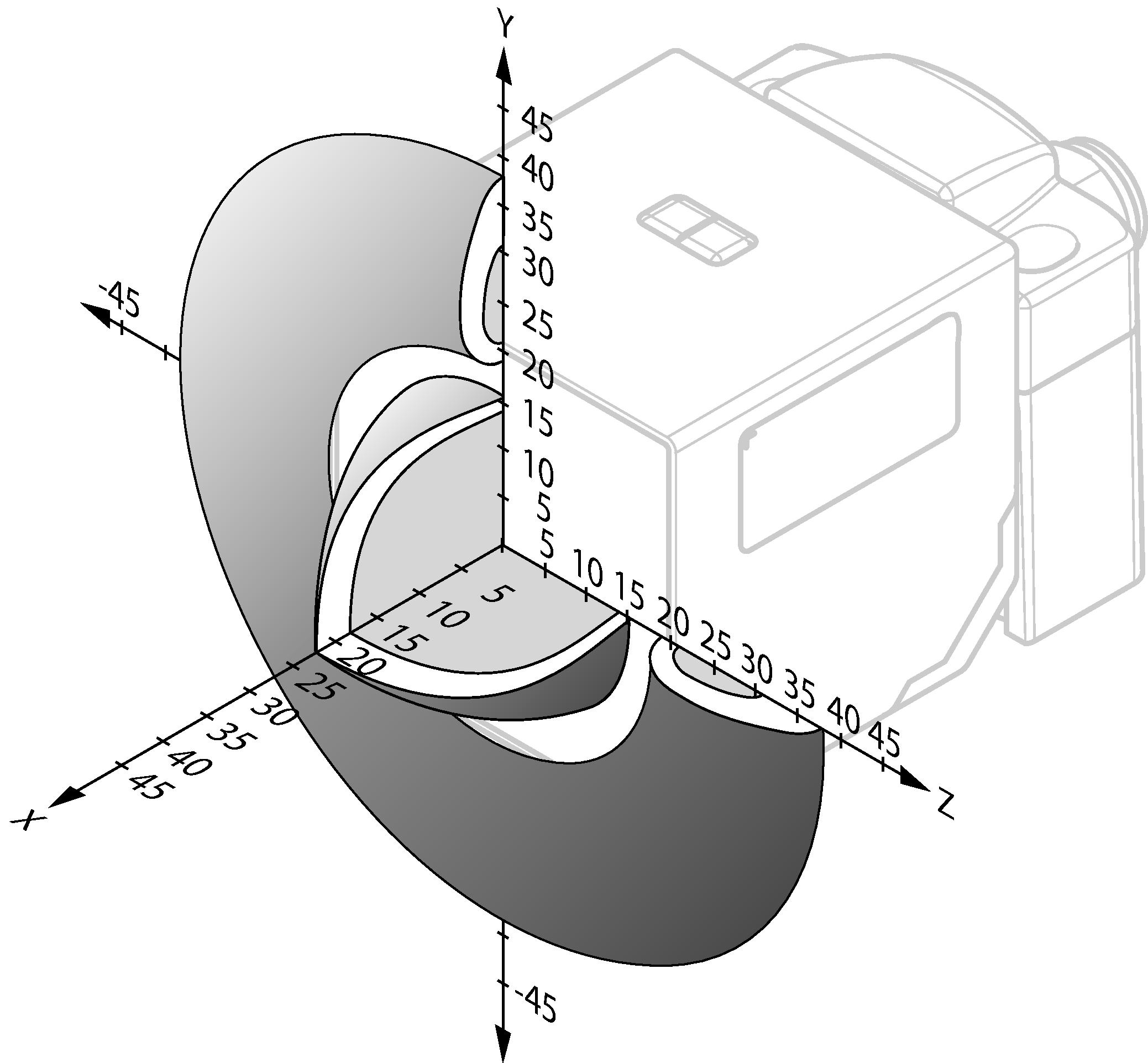
For a side approach direction for the actuator and safety switch, a minimum distance of s = 6 mm must be maintained so that the actuating range of the side lobes is not entered.
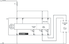
Connector assignment
| Plug connector (view of connection side) | Pin | Designation | Function | Connecting cable conductor coloring |
|---|---|---|---|---|
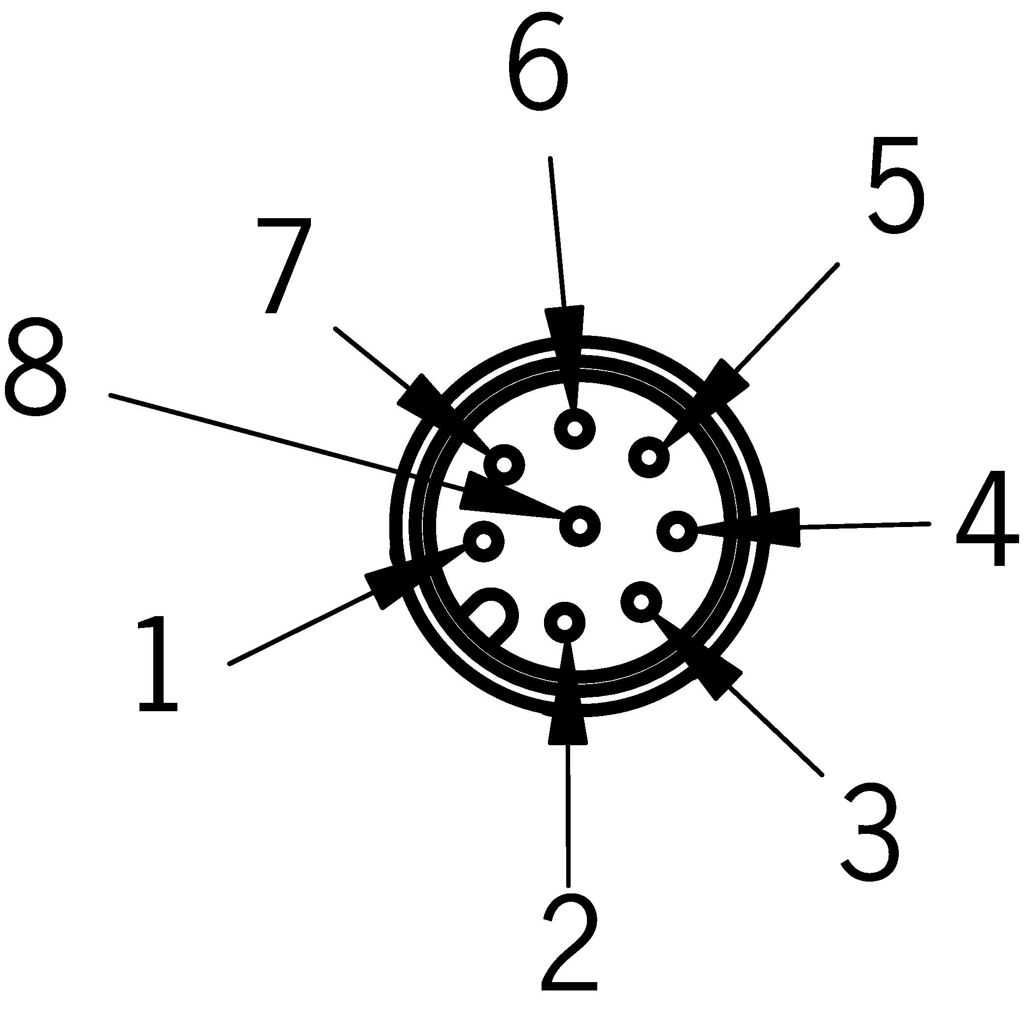 | 1 | IB | Enable input for channel 2 | WH |
| 2 | UB | Power supply, DC 24 V | BN | |
| 3 | OA | Safety output, channel 1 | GN | |
| 4 | OB | Safety output, channel 2 | YE | |
| 5 | OUT | Monitoring output | GY | |
| 6 | IA | Enable input for channel 1 | PK | |
| 7 | 0 V | Ground, DC 0 V | BU | |
| 8 | RST | Reset input | RD |
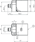
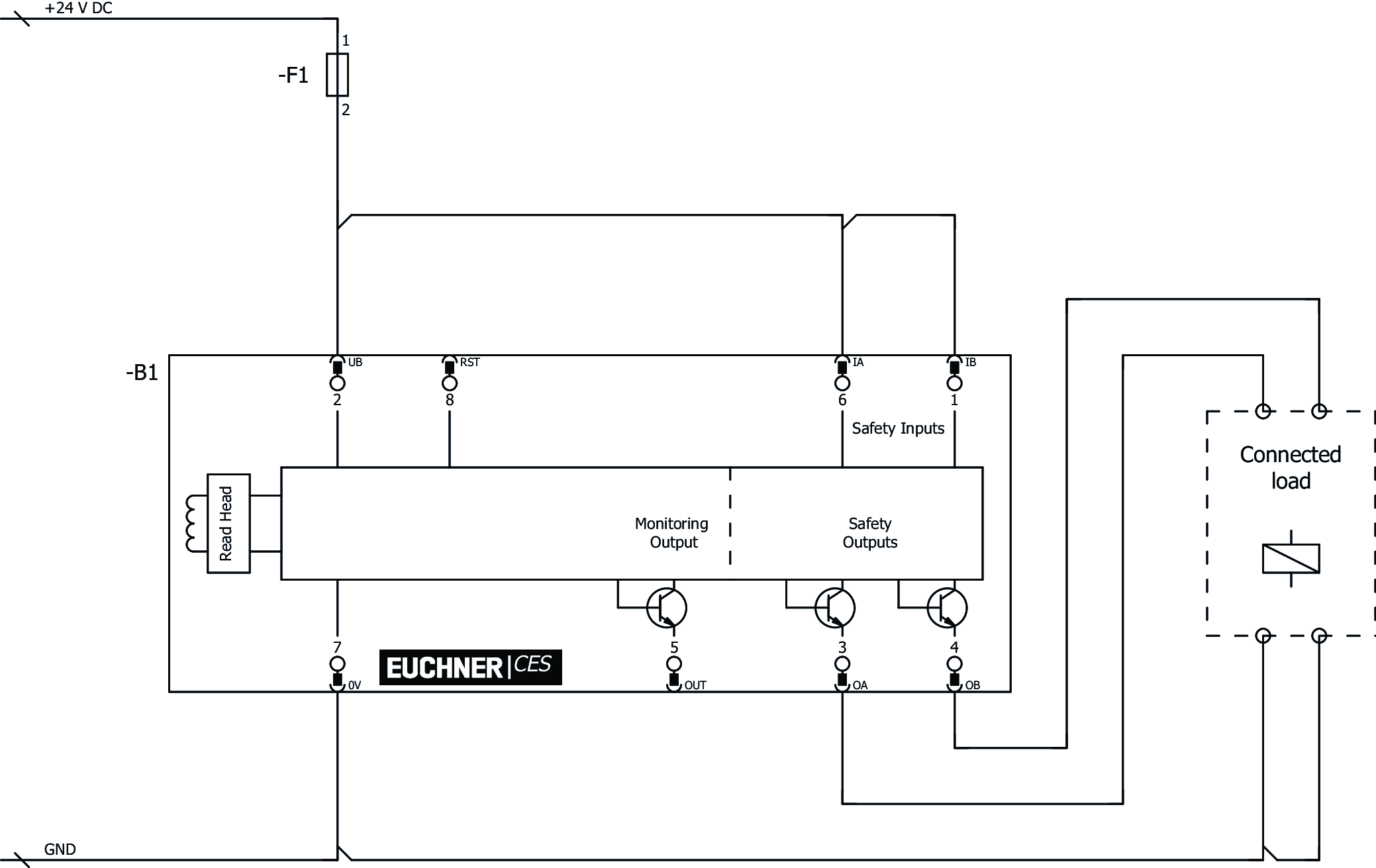
Dimensional drawings
| 1 | LED status indication |
| 2 | Active face |
Connection examples
Technical data
Approvals


Workspace
| Repeat accuracy R | 10 % |
Electrical connection values
| Fuse | |
| external (operating voltage) | 0.25 ... 8 A |
| Rated insulation voltage Ui | 75 V (Tested up to 75 V by employers' liability insurance association) |
| Rated impulse voltage Uimp | 1.5 kV |
| Operating voltage DC | |
| UB | 24 V DC -15% ... +15% reverse polarity protected, regulated, residual ripple<5%, PELV |
| Turn-on time | |
| Safety outputs | max. 400 ms |
| EMC protection requirements | Acc. to EN IEC 60947-5-3 |
| Risk time according to EN 60947-5-3 | max. 260 ms |
| Risk time according to EN 60947-5-3, extension for each additional device | max. 5 ms |
| Safety class | III |
| Current consumption | |
| no load on outputs | max. 50 mA |
| Degree of contamination (external, according to EN 60947-1) | 3 |
| Monitoring output OUT | |
| Output type | p-switching, short circuit-proof |
| Output voltage | 0.8 x UB ... UB V DC (Values at a switching current of 50 mA without taking into account the cable lengths.) |
| Switching current | max. 200 mA |
| Safety outputs OA / OB | |
| Output type | Semiconductor outputs, p-switching, short circuit-proof |
| Output voltage | |
| HIGH U(OA,OB) | UB-1.5 ... UB V DC (Values at a switching current of 50 mA without taking into account the cable lengths.) |
| LOW U(OA,OB) | 0 ... 1 V DC |
| rated conditional short-circuit current | 100 A |
| Discrepancy time | max. 10 ms |
| Utilization category | |
| DC-13 | 24V 400mA (Caution: outputs must be protected with a free-wheeling diode in case of inductive loads.) |
| Off-state current Ir | max. 0.25 mA |
| Switching current | |
| per safety output | 1 ... 400 mA |
| Test pulse duration | max. 1 ms |
Mechanical values and environment
| Connection type | M12 plug connector, 8-pin |
| Tightening torque | |
| Fixing screws | max. 1 Nm |
| Ready delay | 10 s |
| Installation orientation | any |
| Switching frequency | max. 1 Hz |
| Mounting distance | min. 40 mm |
| Shock and vibration resistance | Acc. to EN IEC 60947-5-3 |
| Degree of protection | IP67 |
| Ambient temperature | -20 ... 55 °C |
| Material | |
| Housing | Plastic, PBT |
Characteristic values according to EN ISO 13849-1 and EN IEC 62061
| PL | Maximum SIL | PFHD | Category | Mission time | |
|---|---|---|---|---|---|
| Monitoring of the guard position | PL e | - | 2.1x10⁻⁹ | 4 | 20 y |
Miscellaneous
| Notices for UL approval | Operation only with UL Class 2 power supply or equivalent measures |
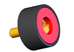
In combination with actuator CES-A-BRN-100251
| Switch-on distance | 27 mm |
| Secured switch-off distance sar | max. 75 mm |
| Secured switching distance sao | min. 20 mm (The values apply to surface mounting of the actuator on steel.) |
| Switching hysteresis | 3 mm (The values apply to surface mounting of the actuator on steel.) |
In combination with actuator CES-A-BDA-18-156935
| Switch-on distance | 19 mm (for surface mounting) |
| Secured switch-off distance sar | max. 45 mm (for surface mounting) |
| Secured switching distance sao | min. 10 mm (for surface mounting) |
| Switching hysteresis | 1 ... 3 mm (for surface mounting) |
In combination with actuator CES-A-BPA-098775
| Switch-on distance | 22 mm (on surface mounting on aluminum. In a non-metallic environment, the typical operating distances increase to 30 mm) |
| Secured switch-off distance sar | max. 58 mm |
| Secured switching distance sao | min. 18 mm |
| Switching hysteresis | 1 ... 2 mm |
In combination with actuator CES-A-BBA-071840
| Switch-on distance | 18 mm |
| Secured switch-off distance sar | max. 45 mm (for surface mounting) |
| Secured switching distance sao | min. 15 mm (for surface mounting) |
| Switching hysteresis | 1 ... 3 mm (for surface mounting) |
Accessories


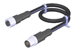
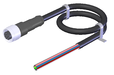

C-M12F05-05X025PU10,0-M12M05-115565
- M12 female plug, 5-pin (angled) to M12 plug connector (straight)
- plug connectors at both ends
- PUR cable
- Cable length 10 m
- with cable exit A (right)
C-M12F05-05X025PU10,0-M12M05-115566
- M12 female plug, 5-pin (angled) to M12 plug connector (straight)
- plug connectors at both ends
- PUR cable
- Cable length 10 m
- with cable exit C (left)
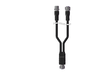
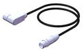
AC-YD-V0,2-SBB-111696
- For series connection of AR/BR safety switches in switch chains without IO-Link evaluation
- Y-distributor M12 with connecting cable, 2 x 5-pin, 1 x 8-pin
- Straight plug connector
- PVC cable
- Cable length 0.2 m
AC-YD-V1,0-SBB-112395
- For series connection of AR/BR safety switches in switch chains without IO-Link evaluation
- Y-distributor M12 with connecting cable, 2 x 5-pin, 1 x 8-pin
- Straight plug connector
- PVC cable
- Cable length 1 m

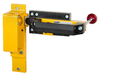
RIEGEL CES-AR-C/F
- Bolt for switch CES-C01
- Steel bolt
- For doors hinged on the left or right
- Bolt with escape lever
- Detent knob in open position
- Ball detent mechanism in closed position
- Suitable for a door gap of approx. 15 mm
- Protective plate for safety switch

RIEGEL CES-AC-AR-C01-AH-SA-C2296
- Bolt for switch CES-C01
- Steel bolt
- For doors hinged on the left or right
- Ball detent mechanism in closed position
- Suitable for a door gap of approx. 7 mm
- Protective plate for safety switch

Downloads
Complete package
Download all important documents with a single click.
Content:
- The operating instructions and any additions to the operating instructions or brief instructions
- Any data sheets to supplement the operating instructions
- The declaration of conformity
Single Documents


Other Documents


CAD data

Ordering data
| Ordernumber | 098941 |
| Item designation | CES-AR-C01-AH-SA |
| Gross weight | 0,19kg |
| Global Trade Item Number (GTIN) | 4047048005433 |
| Customs tariff number | 85365019000 |
| ECLASS | 27-27-24-03 Safety-related transponder switch |
