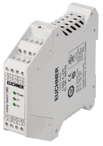
CMS-E-ER (Rend. sz. 099182)
Válasszon tartalmat
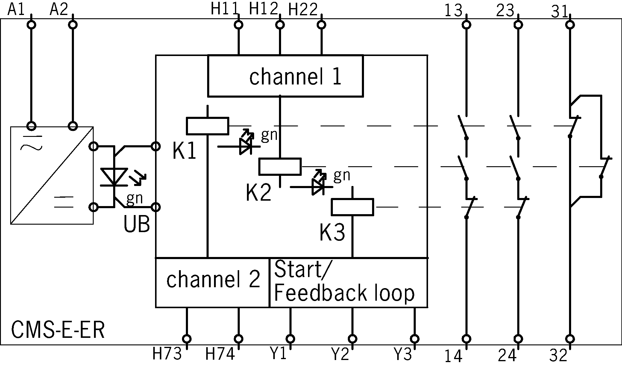
Evaluation unit CMS-E-ER, 2 safety contacts, 1 auxiliary contact, 1 feedback loop can be connected
- Up to 30 read heads can be connected
- 2 safety contacts
- 1 auxiliary contact
- 1 feedback loop can be connected
- Start automatic/monitored/not monitored
Ismertetés
Functional description
The evaluation unit CMS-E-ER is suitable for the direct connection of up to 30 read heads.
Category/PL according to EN ISO 13849-1
- Category 4/PL e with only one read head connected
- Max. category 3/PL d with more than one read head connected
Notice:
At low approach speeds in the z direction, the time offset when switching the reed contacts must not be more than 0.6 ms.
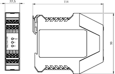

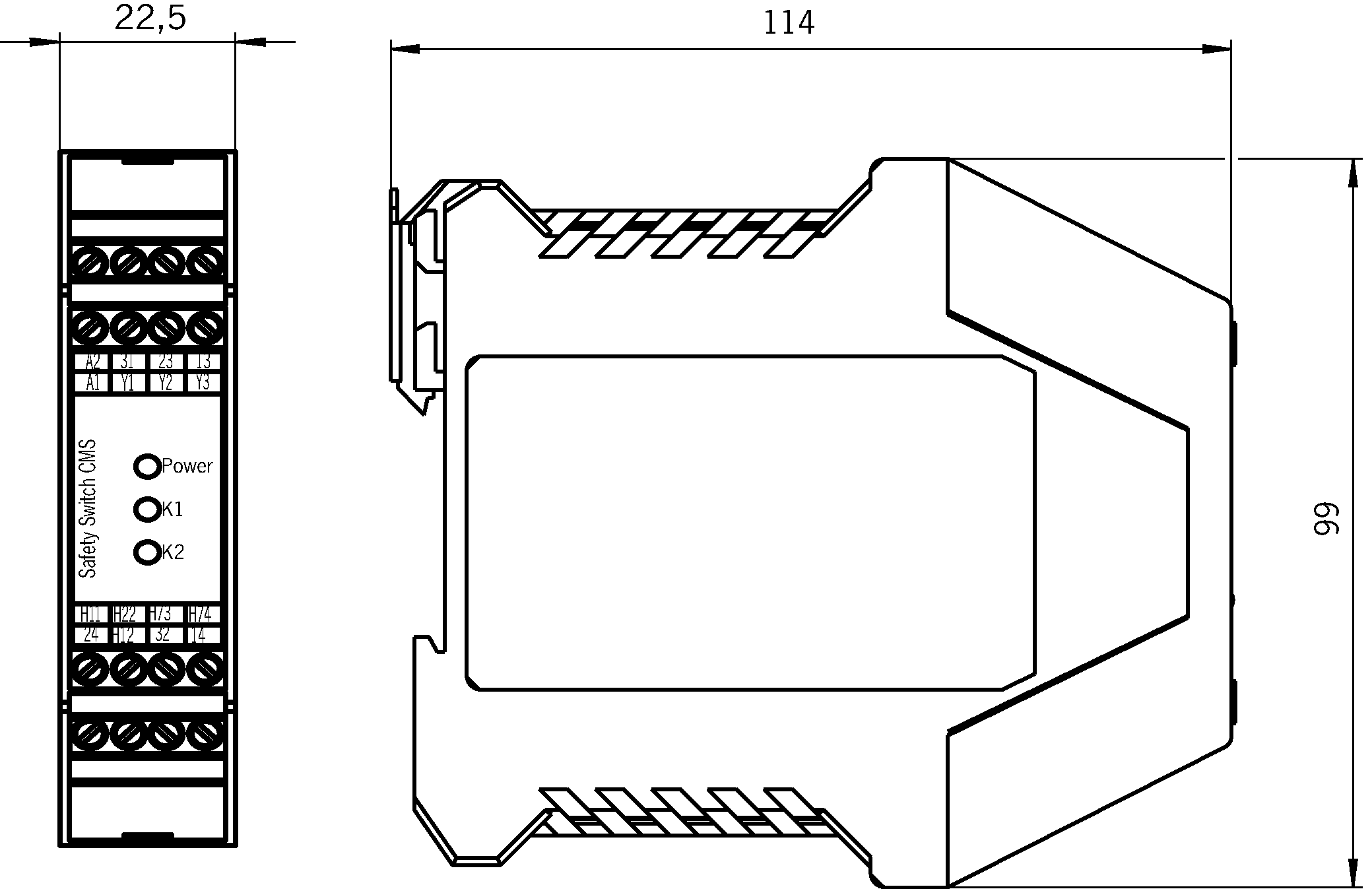
Dimensional drawings
Connection examples
Műszaki adatok
Approvals


Operating and display elements
| LED display | 1 indicator LED Power (UB) and 2 status indicators for the read heads (K1/K2) |
Electrical connection values
| Fuse | |||||||||||||
| External contact fuse (safety circuit) acc. to EN IEC 60269-1 | 4 A gG | ||||||||||||
| Protection internal (operating voltage UB) | 0.75 A Automatically resetting fuse PTC | ||||||||||||
| Connection cross section | 0.14 ... 2.5 mm² | Outputs | |||||||||||
| |||||||||||||
| Rated insulation voltage Ui | 250 V | ||||||||||||
| Operating voltage | |||||||||||||
| AC/DC | -10% ... 24 ... +10% V (All the electrical connections must either be isolated from the mains supply by a safety transformer according to EN 61558-2-6 with limited output voltage in the event of a fault, or by other equivalent insulation measures.) | ||||||||||||
| Utilization category | |||||||||||||
| AC-1 | 3A, 230V; 3A, 24V (Max. switching current per contact) | ||||||||||||
| DC-13 | 1.5A, 24V (Max. switching current per contact) | ||||||||||||
| AC-15 | 0.9A , 240V and 0.9A , 24V (Max. switching current per contact) | ||||||||||||
| Risk time according to EN 60947-5-3 | max. 20 ms | ||||||||||||
| Switching load | |||||||||||||
| According to UL class 2 | Input: 24 V AC/DC; output: 30 V AC, 24 V DC | ||||||||||||
| Switching capacity (VA) | |||||||||||||
| Safety contacts 13/14, 23/24 | max. 720 VA | ||||||||||||
| Switching voltage | |||||||||||||
| Safety contacts 13/14, 23/24 | max. AC 240 V | ||||||||||||
| Switching current | |||||||||||||
| Auxiliary contacts 31/32 | max. 1500 mA at DC 24 V | ||||||||||||
| Safety contacts 13/14, 23/24 | 10 ... 3000 mA at DC 24 V | ||||||||||||
| Current consumption | |||||||||||||
| at DC 24 V | 10 ... 110 mA | ||||||||||||
| Degree of contamination (external, according to EN 60947-1) | 2 | ||||||||||||
Mechanical values and environment
| Approach direction | Z (If the approach speed is low, the approach direction Z should be avoided.) |
| Connection type | Connection terminals |
| Mechanical life | 10 x 10⁶ |
| Mounting type | Mounting rail TH 35 (EN IEC 60715) |
| Degree of protection | Terminals IP20 / housing IP40 |
| Ambient temperature | 0 ... 55 °C |
| Material | |
| Housing | Polyamide PA6.6 |
Characteristic values according to EN ISO 13849-1 and EN IEC 62061
| Number of switching cycles | |
| ≤ 1 A at 24 V DC | 70000 1/y |
| ≤ 0.1 A at 24 V DC | 166000 1/y |
| Mission time | 20 y (This value is dependent on the number of switching cycles and the switching current.) |
| Monitoring of the guard position with 1 read head | |
| Category | 4 (This value is dependent on the number of switching cycles and the switching current.) |
| Performance Level | PL e (This value is dependent on the number of switching cycles and the switching current.) |
| PFHD | 2.5 x 10⁻⁸ (This value is dependent on the number of switching cycles and the switching current.) |
| Monitoring of the guard position with>1 read head | |
| Category | 3 (This value is dependent on the number of switching cycles and the switching current.) |
| Performance Level | PL d (This value is dependent on the number of switching cycles and the switching current. This value applies to cables laid with protection. The following applies if cables are laid without protection and more than one door must be opened frequently or if cables are laid without protection and more than 5 doors are connected in series: Performance Level = PL c, PFHd = 1.1E-6. On this topic, also see EN ISO 14119:2014, section 8.6, and ISO TR 24119. Evaluation of the diagnostic coverage according to ISO TR 24119 must result in at least the value 'low' in order to achieve PL d.) |
| PFHD | 1.0 x 10⁻⁷ (This value is dependent on the number of switching cycles and the switching current. This value applies to cables laid with protection. The following applies if cables are laid without protection and more than one door must be opened frequently or if cables are laid without protection and more than 5 doors are connected in series: Performance Level = PL c, PFHd = 1.1E-6. On this topic, also see EN ISO 14119:2014, section 8.6, and ISO TR 24119. Evaluation of the diagnostic coverage according to ISO TR 24119 must result in at least the value 'low' in order to achieve PL d) |
Miscellaneous
| in compliance with | EN ISO 13849-1: 2015; EN ISO 13849-2:2012; EN 50178: 1997; EN 60204-1: 2006/A1: 2009; EN ISO 13850: 2015; EN 14119:2013; EN 6100-6-2: 2005; EN 6100-6-3: 2007/A1: 2011; EN 60947-5-3: 2013 |
In combination with read head CMS-RH-BYB-03VL, CMS-RH-BYB-05VL and actuator CMS-MH-BB
| Secured switch-off distance sar | max. 13 mm (The assured release distance s_ar corresponds to the reset distance.) |
| Secured switching distance sao | |
| with center offset m=0 | min. 6 mm (Figure only applies if there is no ferromagnetic material in the vicinity of the read head and the actuator.) |
| Center offset | |
| at s = 3 mm read distance | 2,5 mm (Figure only applies if there is no ferromagnetic material in the vicinity of the read head and the actuator.) |
In combination with read head CMS-R-CXC-03V, CMS-R-CXC-05V, CMS-R-CXC-05P, CMS-R-CXC-SC and actuator CMS-M-CA
| Secured switch-off distance sar | max. 14 mm (The assured release distance s_ar corresponds to the reset distance.) |
| Secured switching distance sao | |
| with center offset m=0 | min. 6 mm (Figure only applies if there is no ferromagnetic material in the vicinity of the read head and the actuator.) |
| Center offset | |
| at s = 3 mm read distance | 2,5 mm (Figure only applies if there is no ferromagnetic material in the vicinity of the read head and the actuator.) |
In combination with read head CMS-R-AXH-03V, CMS-R-AXH-05V, CMS-R-AXH-SC, CMS-R-AXH-05P and actuator CMS-M-AC
| Secured switch-off distance sar | max. 31 mm (The assured release distance s_ar corresponds to the reset distance.) |
| Secured switching distance sao | |
| with center offset m=0 | min. 6 mm (Figure only applies if there is no ferromagnetic material in the vicinity of the read head and the actuator.) |
| Center offset | |
| at s = 3 mm read distance | 2,5 mm (Figure only applies if there is no ferromagnetic material in the vicinity of the read head and the actuator.) |
In combination with read head CMS-R-EXM-03V, CMS-R-EXM-05V, CMS-R-EXM-SC and actuator CMS-M-EF
| Secured switch-off distance sar | max. 17 mm (The assured release distance s_ar corresponds to the reset distance.) |
| Secured switching distance sao | |
| with center offset m=0 | min. 6 mm (Figure only applies if there is no ferromagnetic material in the vicinity of the read head and the actuator.) |
| Center offset | |
| at s = 3 mm read distance | 2,5 mm (Figure only applies if there is no ferromagnetic material in the vicinity of the read head and the actuator.) |
In combination with read head CMS-R-BXI-03V, CMS-R-BXI-05V, CMS-R-BXI-SC, CMS-R-BXI-07P and actuator CMS-M-BD
| Secured switch-off distance sar | max. 12 mm (The assured release distance s_ar corresponds to the reset distance.) |
| Secured switching distance sao | |
| with center offset m=0 | min. 3 mm (Figure only applies if there is no ferromagnetic material in the vicinity of the read head and the actuator.) |
| Center offset | |
| at s = 3 mm read distance | 2,5 mm (Figure only applies if there is no ferromagnetic material in the vicinity of the read head and the actuator.) |
In combination with read head CMS-RH-AYA-03VL, CMS-RH-AYA-05VL and actuator CMS-MH-AA
| Secured switch-off distance sar | max. 20 mm (The assured release distance s_ar corresponds to the reset distance.) |
| Secured switching distance sao | |
| with center offset m=0 | min. 10 mm (Figure only applies if there is no ferromagnetic material in the vicinity of the read head and the actuator.) |
| Center offset | |
| at s = 3 mm read distance | 2,5 mm (Figure only applies if there is no ferromagnetic material in the vicinity of the read head and the actuator.) |
Tartozékok
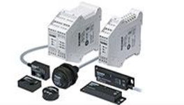
CMS read heads


Letöltések
Teljes csomag
Minden fontos dokumentum letöltése egyetlen kattintással.
Tartalom:
- A használati utasítás és a használati utasítás vagy a rövid utasítás kiegészítései
- A használati utasítást kiegészítő adatlapok
- A megfelelőségi nyilatkozat
Teljes csomag letöltése (ZIP, 2,2 MB)
Egyedi dokumentumok
Declarations of conformity
EU-Konformitätserklärung

Dok. sz.
Változat
Nyelv
Méret
EU-Konformitätserklärung
Dok. sz.
EDC2112987
Változat
Nyelv
Méret
0,2 MB
UKCA-Konformitätserklärung

Dok. sz.
Változat
Nyelv
Méret
UKCA-Konformitätserklärung
Dok. sz.
EDC20001569
Változat
Nyelv
Méret
0,1 MB
Instructions
Operating Instructions Evaluation Unit CMS-E-ER


Dok. sz.
Változat
Nyelv
Méret
Operating Instructions Evaluation Unit CMS-E-ER
Mode d’emploi Analyseur CMS-E-ER
Manual de instrucciones Unidad de evaluación CMS-E-ER
Betriebsanleitung Auswertegerät CMS-E-ER
Mode d’emploi Analyseur CMS-E-ER
Manual de instrucciones Unidad de evaluación CMS-E-ER
Betriebsanleitung Auswertegerät CMS-E-ER
Dok. sz.
2102344
Változat
12-11/23
Nyelv
Méret
2,1 MB
Betriebsanleitung Auswertegerät CMS-E-ER
Dok. sz.
2102344
Változat
12-11/23
Nyelv
Méret
0,6 MB

Egyéb dokumentumok
Approvals and certificates

TÜV SÜD Italia_CMS-E-E(F)R_TUV IT 0948 25 MAC 480 B

Dok. sz.
Változat
Nyelv
Méret
TÜV SÜD Italia_CMS-E-E(F)R_TUV IT 0948 25 MAC 480 B
Dok. sz.
Változat
Nyelv
Méret
1,1 MB
c UL us

Dok. sz.
Változat
Nyelv
Méret
c UL us
Dok. sz.
Változat
Nyelv
Méret
1,0 MB
Sales documents
Interrupteurs de sécurité à codage magnétique CMS

Dok. sz.
Változat
Nyelv
Méret
Interrupteurs de sécurité à codage magnétique CMS
Dok. sz.
090606
Változat
10-11/20
Nyelv
Méret
5,8 MB


Rendelési adatok
| Rend. sz. | 099182 |
| Cikk neve | CMS-E-ER |
| Súly | 0,225kg |
| Vámtarifaszám | 85364110 |
| ECLASS | 27-27-24-02 Safety-related magnetic proximity switch |