CES-AZ-ABS-01B (Rend. sz. 100064)
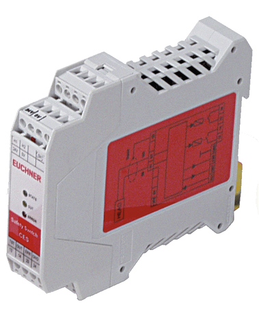
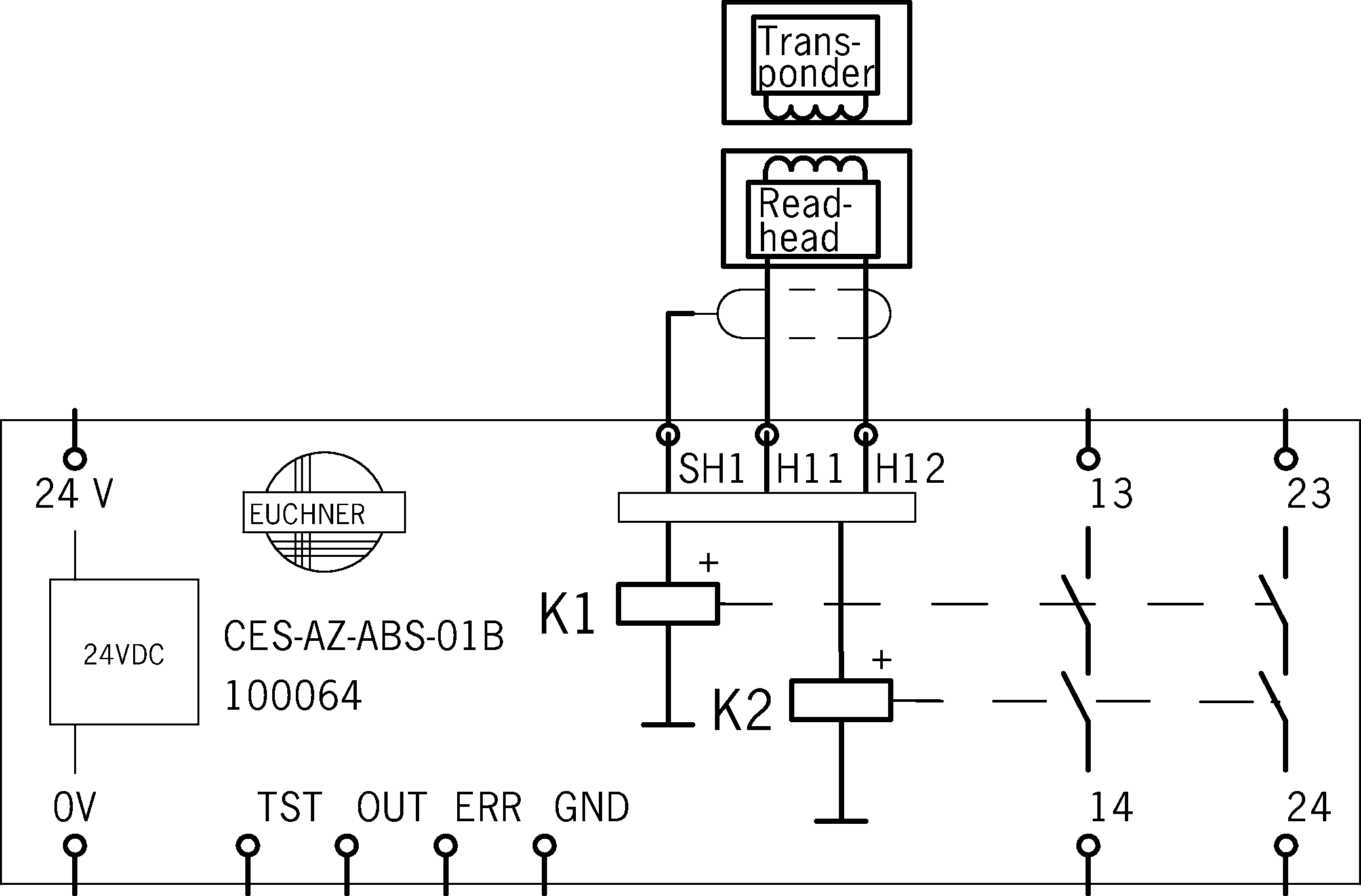
Evaluation unit CES-AZ-ABS-01B (for 1 read head)
- 1 read head can be connected
- 2 safety contacts (relay contacts)
- 1 internal normally open contact per safety contact
- Unicode evaluation unit
- Category 3 / PL e according to EN ISO 13849-1
Ismertetés
Unicode evaluation unit
Each actuator is highly coded (unicode). The evaluation unit detects only actuators that have been taught-in. Max. 8 actuators can be taught-in.
Guard lock monitoring
Evaluation units in the series CES-AZ make it possible to use read heads with integrated guard locking for the protection of personnel during overtraveling machine movements. You will find suitable read heads in the accessories
Category according to EN ISO 13849-1
Due to two redundant safety paths (relay contacts) with 2 internal, monitored normally open contacts per safety path, suitable for:
- Category 3 / PL e according to EN ISO 13849-1
To achieve the stated category, both safety contacts must always be evaluated.
Actuating range
The evaluation unit has the standard actuating range that, e.g., permits larger tolerances in the alignment of read head and actuator. Wherever a smaller actuating range is required, the version with reduced actuating range (CES-A-...-01) can be used.
Additional connections
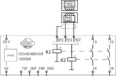
TST | Input for self-test |
OUT | Monitoring output (semiconductor) |
ERR | Diagnostic output |
GND | Connected internally to 0V (not for high currents) |
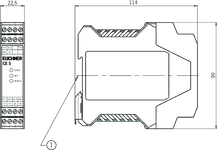
Dimensional drawings
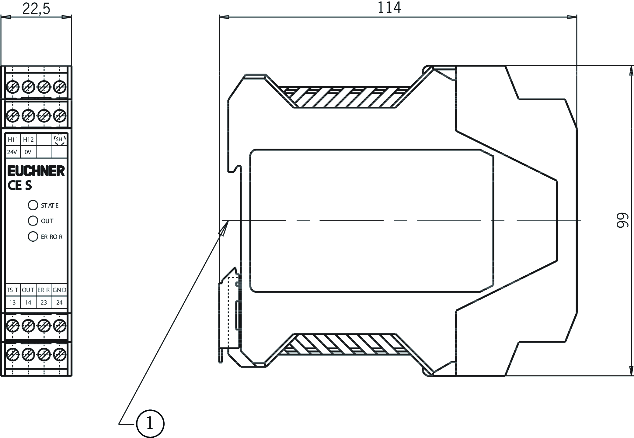
| 1 | Suitable for 35 mm mounting rail according to EN 60715 |
Connection examples
Műszaki adatok
Approvals


Workspace
| Repeat accuracy R | |
| according to EN 60947-5-2 | 10 % |
Operating and display elements
| LED display | |
| Safety contacts status | |
| Status LED | |
| Diagnostics LED |
Electrical connection values
| Fuse | |
| external (operating voltage UB) | 0.25 ... 8 A |
| Connection cross section | |
| Screw terminals | 0.25 ... 2.5 mm² |
| Operating voltage DC | |
| UB | 21 ... 24 ... 27 V DC regulated, residual ripple<5% |
| EMC protection requirements | Acc. to EN IEC 60947-5-3 |
| Current consumption | |
| (with relay energized) | 150 mA (without taking into account the load currents at the monitoring outputs) |
| Degree of contamination (external, according to EN 60947-1) | 2 |
| Inputs: test input TST | |
| Input voltage | |
| LOW | 0 ... 2 V DC |
| HIGH | 15 ... UB V DC |
| Monitoring outputs: diagnostics ERR, door monitoring output OUT | |
| Output type | Semiconductor output, p-switching |
| Output voltage | 0.8 x UB ... UB V DC |
| Output current | max. 20 mA |
| Safety contacts 13/14, 23/24 | |
| Fuse | |
| external (safety circuit) according to EN 60269-1 | 6 AgG or 6 A circuit breaker (characteristic B or C) |
| Output type | Relay contacts, floating |
| rated conditional short-circuit current | 100 A |
| Rated insulation voltage Ui | 250 V |
| Rated impulse voltage Uimp | 4 kV |
| Discrepancy time | |
| (between the operating points of both relays) | max. 25 ms |
| Utilization category | |
| AC-12 | 30V 6A |
| DC-12 | 60V 0.3A |
| DC-12 | 30V 6A |
| AC-15 | 230V 2A |
| DC-13 | 24V 3A |
| AC-12 | 60V 0.3A |
| Switching load | |
| according to c UL us | Class 2 max. 30 V AC / Class 2 max. 60 V DC |
| Switching current | |
| at switching voltage AC 5 ... 230 V | 10 ... 2000 mA |
| at switching voltage AC/DC 21 ... 60 V | 1 ... 300 mA |
| at switching voltage AC/DC 5 ... 30 V | 10 ... 6000 mA |
Mechanical values and environment
| Connection type | plug-in screw terminals, coded |
| Number of read heads | 1 read head can be connected |
| Ready delay | max. 3 s (After the operating voltage is switched on, the relay outputs are switched off and the door monitoring output is set to LOW level during the ready delay.) |
| Switching frequency | max. 1 Hz (If the current load is>100 mA, a switching frequency of 0.1 Hz should not be exceeded as this will affect the mechanical life of the relay contacts.) |
| Storage temperature | -25 ... 70 °C |
| Atmospheric humidity | |
| not condensing | max. 80 % rH |
| Mounting distance | |
| between evaluation units | min. 10 mm |
| Mounting type | Mounting rail TH 35 (EN IEC 60715) |
| Response time | |
| after change in the actuation status | max. 180 ms (Corresponds to the risk time according to EN 60947-5-3. This is the maximum OFF time for the safety outputs following removal of an actuator.) |
| Degree of protection | IP20 |
| Ambient temperature | |
| at UB = 24 V DC | -20 ... 55 °C |
| Dwell time | min. 0.5 s (The dwell time of an actuator inside and outside the actuating range must be at least 0.5 s to ensure safe detection of internal faults in the evaluation unit (self-monitoring).) |
| Material | |
| Housing | Plastic PA6.6 |
| Safety contacts 13/14, 23/24 | |
| Number of safety contacts | 2 Relay with internally monitored contacts |
| Mechanical life | |
| Operating cycles (relay) | 10 x 10⁶ |
Characteristic values according to EN ISO 13849-1 and EN IEC 62061
| Number of switching cycles | |
| ≤ 0.1 A at 24 V DC | max. 760000 1/y |
| ≤ 3 A at 24 V DC | max. 34600 1/y |
| ≤ 1 A at 24 V DC | max. 153000 1/y |
| Mission time | 20 y (This value is dependent on the number of switching cycles and the switching current.) |
| Monitoring of the guard position | |
| Diagnostic Coverage (DC) | 90 % |
| Category | 3 (This value is dependent on the number of switching cycles and the switching current.) |
| Performance Level | PL e (This value is dependent on the number of switching cycles and the switching current.) |
| PFHD | 4.3 x 10⁻⁸ (This value is dependent on the number of switching cycles and the switching current.) |
Miscellaneous
| Notices for UL approval | Operation only with UL Class 2 power supply or equivalent measure. |
In combination with read head CES-A-LNA-SC-077715, CES-A-LNA-05P-077806, CES-A-LNA-10P-077807, CES-A-LNA-05V-071845, CES-A-LNA-10V-071846, CES-A-LNA-15V-071847, CES-A-LNA-25V-071975, CES-A-LNA-15P-084682, CES-A-LCA-10V and actuator CES-A-BDA-20
| Actuator distance s | |
| Minimum distance for side approach direction | min. 4 mm (on mounting in non-metallic environment) |
| Switch-on distance | |
| with center offset m=0 | 16 mm (on mounting in non-metallic environment) |
| Secured switch-off distance sar | max. 33 mm |
| Secured switching distance sao | |
| with center offset m=0 | min. 11 mm (on mounting in non-metallic environment) |
| Switching hysteresis | 0.5 ... 2 mm (on mounting in non-metallic environment) |
In combination with read head CES-A-LNA-SC-077715, CES-A-LNA-05P-077806, CES-A-LNA-10P-077807, CES-A-LNA-05V-071845, CES-A-LNA-10V-071846, CES-A-LNA-15V-071847, CES-A-LNA-25V-071975, CES-A-LNA-15P-084682, CES-A-LCA-10V and actuator CES-A-BBA-071840, CES-A-BCA
| Actuator distance s | |
| Minimum distance for side approach direction | min. 3 mm |
| Switch-on distance | |
| with center offset m=0 | 15 mm (for surface mounting of the read head and the actuator) |
| Secured switch-off distance sar | max. 26 mm |
| Secured switching distance sao | |
| with center offset m=0 | min. 10 mm (for surface mounting of the read head and the actuator) |
| Switching hysteresis | 0.5 ... 2 mm (for surface mounting of the read head and the actuator) |
In combination with read head CES-A-LMN-SC
| Mounting distance | |
| between read heads | min. 20 mm |
In combination with read head CES-A-LQA-SC and actuator CES-A-BBA-071840, CES-A-BCA
| Switch-on distance | |
| with vertical approach direction (center offset m = 0) | 15 mm (for surface mounting of the read head and the actuator) |
| for side approach direction (distance in x direction 8 mm) | +/- 22 mm (for surface mounting of the read head and the actuator) |
| Secured switch-off distance sar | max. 47 mm |
| Secured switching distance sao | |
| with vertical approach direction (center offset m = 0) | min. 10 mm (for surface mounting of the read head and the actuator) |
| for side approach direction (distance in x direction 8 mm) | min. +/- 18 mm (for surface mounting of the read head and the actuator) |
| Switching hysteresis | |
| for side approach direction (distance in x direction 8 mm) | 1 ... 1.8 mm (for surface mounting of the read head and the actuator) |
| with vertical approach direction (center offset m = 0) | 2 ... 3 mm (for surface mounting of the read head and the actuator) |
In combination with read head CES-A-LQA-SC
| Mounting distance | |
| between read heads | min. 80 mm |
In combination with read head CES-A-LNA-SC-077715, CES-A-LNA-05P-077806, CES-A-LNA-10P-077807, CES-A-LNA-05V-071845, CES-A-LNA-10V-071846, CES-A-LNA-15V-071847, CES-A-LNA-25V-071975, CES-A-LNA-15P-084682, CES-A-LCA-10V
| Mounting distance | |
| between read heads | min. 50 mm |
In combination with read head CES-A-LMN-SC and actuator CES-A-BMB
| Actuator distance s | |
| Minimum distance for side approach direction | min. 1.2 mm |
| Switch-on distance | |
| with center offset m=0 | 5 mm (for surface mounting of the read head in steel) |
| Secured switch-off distance sar | max. 10 mm |
| Secured switching distance sao | |
| with center offset m=0 | min. 3.5 mm (for surface mounting of the read head in steel) |
| Switching hysteresis | 0.1 ... 0.3 mm (for surface mounting of the read head in steel) |
In combination with read head CES-A-LQA-SC and actuator CES-A-BQA
| Switch-on distance | |
| with vertical approach direction (center offset m = 0) | 23 mm (for surface mounting of the read head and the actuator) |
| for side approach direction (distance in x direction 10 mm) | +/- 28 mm (for surface mounting of the read head and the actuator) |
| Secured switch-off distance sar | max. 60 mm |
| Secured switching distance sao | |
| for side approach direction (distance in x direction 10 mm) | min. +/- 24 mm (for surface mounting of the read head and the actuator) |
| with vertical approach direction (center offset m = 0) | min. 16 mm (for surface mounting of the read head and the actuator) |
| Switching hysteresis | |
| for side approach direction (distance in x direction 10 mm) | 1 ... 1.3 mm (for surface mounting of the read head and the actuator) |
| with vertical approach direction (center offset m = 0) | 2 ... 3 mm (for surface mounting of the read head and the actuator) |
Tartozékok

CEM-A-LE05K-S2
- Read head with guard locking without guard lock monitoring
- Locking force 650 N
- With remanence
- Up to category 4 according to EN ISO 13849-1
- Two safety screws M5x16 included
CEM-A-LE05K-S1-10P
- Read head with guard locking without guard lock monitoring
- Locking force 650 N
- With remanence
- Connection, CES evaluation unit: Cable 10 m, PUR
- Connection, solenoid operating voltage: M8 male plug
- Up to category 4 according to EN ISO 13849-1


Letöltések
Teljes csomag
Minden fontos dokumentum letöltése egyetlen kattintással.
Tartalom:
- A használati utasítás és a használati utasítás vagy a rövid utasítás kiegészítései
- A használati utasítást kiegészítő adatlapok
- A megfelelőségi nyilatkozat
Egyedi dokumentumok


Egyéb dokumentumok


Rendelési adatok
| Rend. sz. | 100064 |
| Cikk neve | CES-AZ-ABS-01B |
| Súly | 0,244kg |
| Global Trade Item Number (GTIN) | 4047048005594 |
| Vámtarifaszám | 85364110 |
| ECLASS | 27-27-24-03 Safety-related transponder switch |