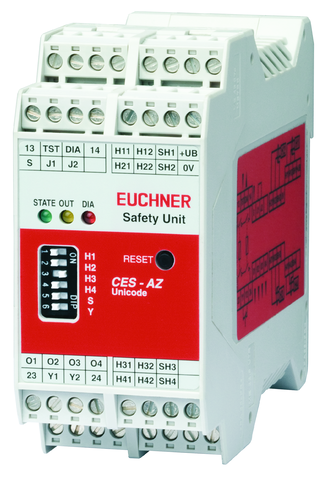
CES-AZ-UES-04B (Rend. sz. 105141)
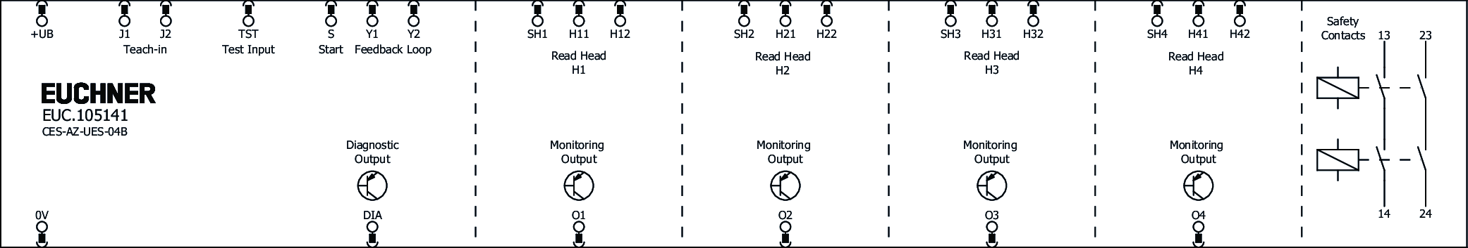
Evaluation unit CES-AZ-UES-04B (for 4 read heads)
- 4 read heads can be connected
- 2 safety outputs (relay contacts with 2 internally connected NO contacts per output)
- Start button and feedback loop can be connected
- Multicode
- Plug-in connection terminals
- Category 4 / PL e according to EN ISO 13849-1
Ismertetés
Multicode evaluation
Every suitable actuator is detected by the evaluation unit.
Guard lock monitoring
Evaluation units in the series CES-AZ make it possible to use read heads with integrated guard locking for the protection of personnel during overtraveling machine movements. You will find suitable read heads in the accessories
Category according to EN ISO 13849-1
Due to two redundant safety paths (relay contacts) with 2 internal, monitored normally open contacts per safety path, suitable for:
- Category 4 / PL e according to EN ISO 13849-1
Each safety path is independently safe.
LED indicator
STATE | Status LED |
DIA | Diagnostics LED |
OUT | Safety output status |
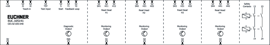
Additional connections
TST | Input for self-test |
O1 ... O4 | Monitoring outputs (semiconductor) |
DIA | Diagnostic output |
Y1, Y2 | Feedback loop |
S | Start button connection (monitoring of the falling edge) |
Important: The plug-in connection terminals are not included and must be ordered separately.
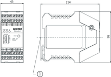
Dimensional drawings
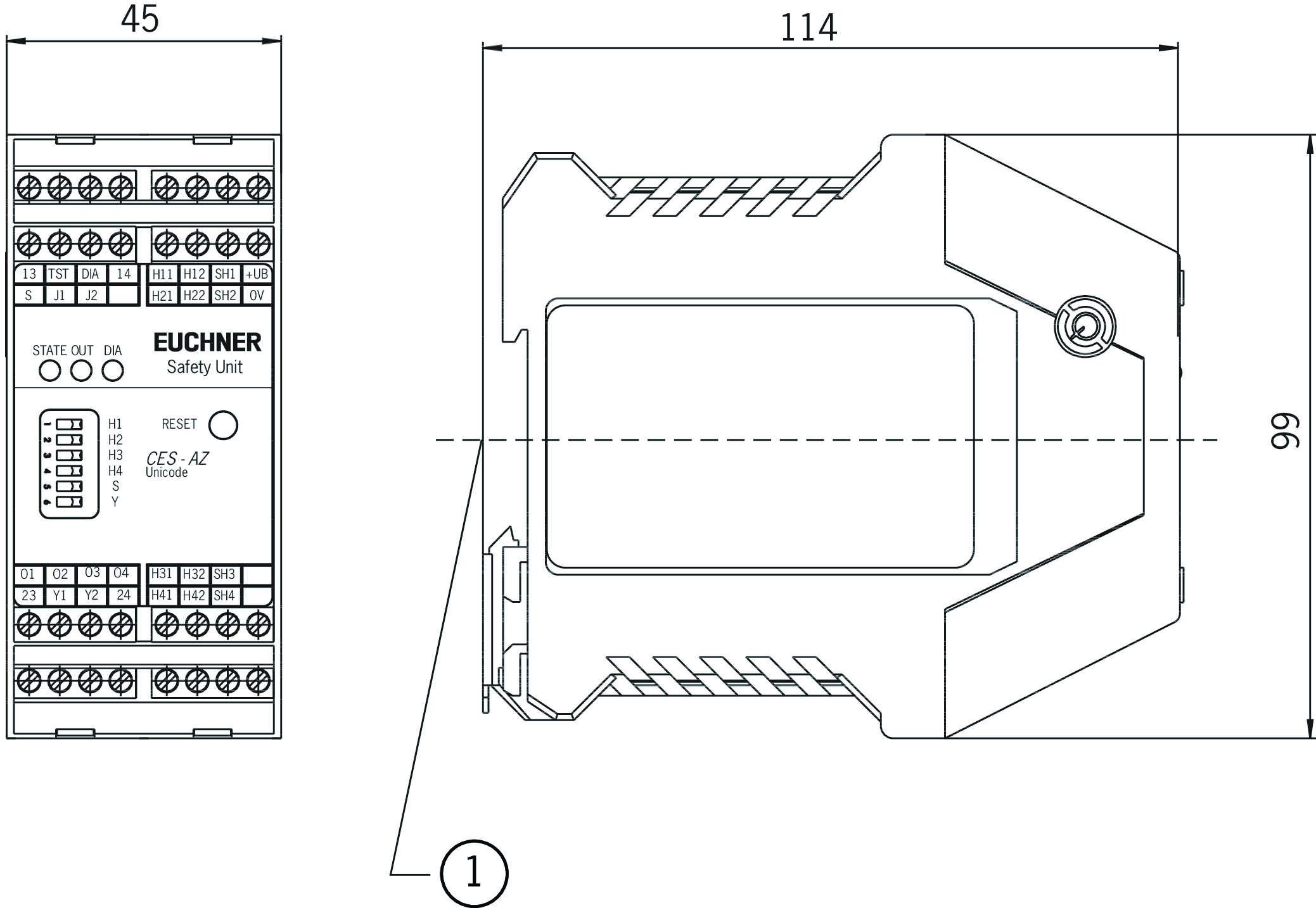
| 1 | Suitable for 35 mm mounting rail according to EN 60715 |
Connection examples
Műszaki adatok
Approvals


Workspace
| Repeat accuracy R | |
| according to EN 60947-5-2 | 10 % |
Operating and display elements
| LED display | |
| Diagnostics LED | |
| Status LED | |
| Safety outputs status |
Electrical connection values
| Fuse | |
| external (operating voltage UB) | 0.25 ... 8 A |
| Connection cross section | |
| plug-in screw/spring terminals | 0.25 ... 2.5 mm² |
| Operating voltage DC | |
| UB | 21 ... 24 ... 27 V DC regulated, residual ripple<5% |
| EMC protection requirements | Acc. to EN IEC 60947-5-3 |
| Current consumption | |
| (with relay energized) | 150 mA (without taking into account the load currents at the monitoring outputs) |
| Current via feedback loop | 5 ... 8 ... 10 mA |
| Degree of contamination (external, according to EN 60947-1) | 2 |
| permissible resistance in feedback loop | max. 600 Ω |
| Inputs: start button S, test input TST | |
| Input voltage | |
| LOW | 0 ... 2 V DC |
| HIGH | 15 ... UB V DC |
| Input current | |
| HIGH | 5 ... 8 ... 10 mA |
| Monitoring outputs: diagnostics DIA, door monitoring outputs O1...O4 | |
| Output type | Semiconductor output, p-switching, short circuit-proof |
| Output voltage | 0.8 x UB ... UB V DC |
| Switching current | max. 20 mA |
| Safety contacts 13/14, 23/24 | |
| Fuse | |
| external (safety circuit) according to EN 60269-1 | 6 AgG or 6 A circuit breaker (characteristic B or C) |
| Output type | Relay contacts, floating |
| rated conditional short-circuit current | 100 A |
| Rated insulation voltage Ui | 250 V |
| Rated impulse voltage Uimp | 4 kV |
| Discrepancy time | |
| (between the operating points of both relays) | max. 25 ms |
| Utilization category | |
| AC-12 | 60V 0.3A |
| DC-13 | 24V 3A |
| DC-12 | 60V 0.3A |
| AC-15 | 230V 2A |
| AC-12 | 30V 6A |
| DC-12 | 30V 6A |
| Switching load | |
| according to c UL us | Class 2 max. 30 V AC / Class 2 max. 60 V DC |
| Switching current | |
| at switching voltage AC/DC 21 ... 60 V | 1 ... 300 mA |
| at switching voltage AC 5 ... 230 V | 10 ... 2000 mA |
| at switching voltage AC/DC 5 ... 30 V | 10 ... 6000 mA |
Mechanical values and environment
| Connection type | plug-in connection terminals, coded (Terminals not included) |
| Number of read heads | max. 4 read heads can be connected |
| Ready delay | 10 ... 12 s (After the operating voltage is switched on, the relay outputs are switched off and the door monitoring outputs are set to LOW level during the ready delay. For visual indication of the delay, the green STATE LED flashes at a frequency of approx. 15 Hz.) |
| Switching frequency | max. 0.25 Hz (In case of monitoring with feedback loop, the actuators must remain outside the actuating range, e.g. with a door open, until the feedback loop is closed.) |
| Atmospheric humidity | |
| not condensing | max. 80 % rH |
| Mounting distance | |
| between evaluation units | min. 10 mm |
| Mounting type | Mounting rail TH 35 (EN IEC 60715) |
| Response time | |
| after change in the actuation status, 3 active actuators | max. 370 ms (Corresponds to the risk time according to EN 60947-5-3. This is the maximum OFF time for the safety outputs following removal of the actuator. In case of EMC interference in excess of the requirements in accordance with EN 60947-5-3, the OFF time can increase to max. 750 ms. After a brief actuation<0.8 s, the switch-on delay can increase to max. 3 s if this is followed immediately by further actuation.) |
| after change in the actuation status, 2 active actuators | max. 290 ms (Corresponds to the risk time according to EN 60947-5-3. This is the maximum OFF time for the safety outputs following removal of the actuator. In case of EMC interference in excess of the requirements in accordance with EN 60947-5-3, the OFF time can increase to max. 750 ms. After a brief actuation<0.8 s, the switch-on delay can increase to max. 3 s if this is followed immediately by further actuation.) |
| Start button actuating duration (for Manual Start operating mode) | min. 250 ms |
| after change in the actuation status, 1 active actuator | max. 210 ms (Corresponds to the risk time according to EN 60947-5-3. This is the maximum OFF time for the safety outputs following removal of the actuator. In case of EMC interference in excess of the requirements in accordance with EN 60947-5-3, the OFF time can increase to max. 750 ms. After a brief actuation<0.8 s, the switch-on delay can increase to max. 3 s if this is followed immediately by further actuation.) |
| after change in the actuation status, 4 active actuators | max. 450 ms (Corresponds to the risk time according to EN 60947-5-3. This is the maximum OFF time for the safety outputs following removal of the actuator. In case of EMC interference in excess of the requirements in accordance with EN 60947-5-3, the OFF time can increase to max. 750 ms. After a brief actuation<0.8 s, the switch-on delay can increase to max. 3 s if this is followed immediately by further actuation.) |
| Start button response delay (for Manual start operating mode) | 200 ... 300 ms |
| Degree of protection | IP20 |
| Ambient temperature | |
| at UB = 24 V DC | -20 ... 55 °C |
| Dwell time | min. 3 s (The dwell time is the time that the actuator must be outside the actuating range.) |
| Material | |
| Housing | Plastic PA6.6 |
| Safety contacts 13/14, 23/24 | |
| Number of safety contacts | 2 Relay with internally monitored contacts |
| Mechanical life | |
| Operating cycles (relay) | 10 x 10⁶ |
Characteristic values according to EN ISO 13849-1 and EN IEC 62061
| PL | Maximum SIL | PFHD | Category | Mission time | ||
|---|---|---|---|---|---|---|
| Monitoring of the guard position | Read head CES-A-L.. CEM-A-L.. | PL e | - | 1.9x10⁻⁸ | 4 | 20 y |
| Only applies for switching voltage 24V DC and switching current up to 0.1 A (max. switching cycles 760,000 1/y) OR up to 1 A (max. switching cycles 153,000 1/y ) OR up to 3 A (max. switching cycles 34,600 1/y) | ||||||
| Monitoring of guard locking | Read head CET.-AX | PL e | - | 1.9x10⁻⁸ | 4 | 20 y |
| Only applies for switching voltage 24V DC and switching current up to 0.1 A (max. switching cycles 760,000 1/y) OR up to 1 A (max. switching cycles 153,000 1/y ) OR up to 3 A (max. switching cycles 34,600 1/y) | ||||||
| PL | Maximum SIL | Category | Mission time | ||
|---|---|---|---|---|---|
| Control of guard locking | Read head CET1-AX | Depending on external control of guard locking | 20 y | ||
Miscellaneous
| Notices for UL approval | Operation only with UL Class 2 power supply or equivalent measures. |
In combination with read head CES-A-LMN-SC and actuator CES-A-BBA-071840
| Switch-on distance | |
| with center offset m=0 | 8 mm A distance of s = 3 mm must be maintained for a side approach direction. (for surface mounting of the read head in metal and metal-free mounting of the actuator) |
| Secured switch-off distance sar | |
| with center offset m=0 | max. 25 mm (for surface mounting of the read head in metal and metal-free mounting of the actuator) |
| Secured switching distance sao | |
| with center offset m=0 | min. 5 mm (for surface mounting of the read head in metal and metal-free mounting of the actuator) |
| Switching hysteresis | |
| with center offset m=0 | 1 ... 1.8 mm (for surface mounting of the read head in metal and metal-free mounting of the actuator) |
In combination with read head CES-A-LQA-SC and actuator CES-A-BBA-071840, CES-A-BCA
| Switch-on distance | |
| with vertical approach direction (center offset m = 0) | 15 mm (for surface mounting of the read head and the actuator) |
| for side approach direction (distance in x direction 8 mm) | +/- 22 mm (for surface mounting of the read head and the actuator) |
| Secured switch-off distance sar | max. 47 mm |
| Secured switching distance sao | |
| for side approach direction (distance in x direction 8 mm) | min. +/- 18 mm (for surface mounting of the read head and the actuator) |
| with vertical approach direction (center offset m = 0) | min. 10 mm (for surface mounting of the read head and the actuator) |
| Switching hysteresis | |
| for side approach direction (distance in x direction 8 mm) | 1 ... 1.8 mm (for surface mounting of the read head and the actuator) |
| with vertical approach direction (center offset m = 0) | 2 ... 3 mm (for surface mounting of the read head and the actuator) |
In combination with read head CES-A-LNA-SC-077715, CES-A-LNA-05P-077806, CES-A-LNA-10P-077807, CES-A-LNA-05V-071845, CES-A-LNA-10V-071846, CES-A-LNA-15V-071847, CES-A-LNA-25V-071975, CES-A-LNA-15P-084682, CES-A-LCA-10V and actuator CES-A-BDA-20
| Actuator distance s | |
| Minimum distance for side approach direction | min. 4 mm (on mounting in non-metallic environment) |
| Switch-on distance | |
| with center offset m=0 | 16 mm (on mounting in non-metallic environment) |
| Secured switch-off distance sar | max. 33 mm |
| Secured switching distance sao | |
| with center offset m=0 | min. 11 mm (on mounting in non-metallic environment) |
| Switching hysteresis | 0.5 ... 2 mm (on mounting in non-metallic environment) |
In combination with read head CES-A-LNN-SC-106601, CES-A-LNN-05V-106602, CES-A-LNN-10V-113294, CES-A-LNN-25V-115107 and actuator CES-A-BBN-106600
| Switch-on distance | |
| in z direction (with center offset x,y = 0), in x direction (with center offset y,z = 0) | 15 mm (for surface mounting of the read head and the actuator) |
| Secured switch-off distance sar | |
| in y direction | max. 100 mm |
| in x or z direction | max. 50 mm |
| Secured switching distance sao | |
| in z direction (with center offset x,y = 0), in x direction (with center offset y,z = 0) | min. 10 mm (for surface mounting of the read head and the actuator) |
| Switching hysteresis | 1 ... 4 mm (for surface mounting of the read head and the actuator) |
In combination with read head CES-A-LQA-SC
| Mounting distance | |
| between read heads | min. 80 mm |
In combination with read head CES-A-LQA-SC and actuator CES-A-BQA
| Switch-on distance | |
| with vertical approach direction (center offset m = 0) | 23 mm (for surface mounting of the read head and the actuator) |
| for side approach direction (distance in x direction 10 mm) | +/- 28 mm (for surface mounting of the read head and the actuator) |
| Secured switch-off distance sar | max. 60 mm |
| Secured switching distance sao | |
| for side approach direction (distance in x direction 10 mm) | min. +/- 24 mm (for surface mounting of the read head and the actuator) |
| with vertical approach direction (center offset m = 0) | min. 16 mm (for surface mounting of the read head and the actuator) |
| Switching hysteresis | |
| for side approach direction (distance in x direction 10 mm) | 1 ... 1.3 mm (for surface mounting of the read head and the actuator) |
| with vertical approach direction (center offset m = 0) | 2 ... 3 mm (for surface mounting of the read head and the actuator) |
In combination with read head CES-A-LNA-SC-077715, CES-A-LNA-05P-077806, CES-A-LNA-10P-077807, CES-A-LNA-05V-071845, CES-A-LNA-10V-071846, CES-A-LNA-15V-071847, CES-A-LNA-25V-071975, CES-A-LNA-15P-084682, CES-A-LCA-10V
| Mounting distance | |
| between read heads | min. 50 mm |
In combination with read head CES-A-LMN-SC and actuator CES-A-BMB
| Actuator distance s | |
| Minimum distance for side approach direction | min. 1.2 mm |
| Switch-on distance | |
| with center offset m=0 | 5 mm (for surface mounting of the read head in steel) |
| Secured switch-off distance sar | max. 10 mm |
| Secured switching distance sao | |
| with center offset m=0 | min. 3.5 mm (for surface mounting of the read head in steel) |
| Switching hysteresis | 0.1 ... 0.3 mm (for surface mounting of the read head in steel) |
In combination with read head CES-A-LMN-SC and actuator CES-A-BDA-18-156935
| Actuator distance s | |
| Minimum distance for side approach direction | min. 3 mm |
| Switch-on distance | |
| with center offset m=0 | 9 mm (for surface mounting of the read head and the actuator) |
| Secured switch-off distance sar | max. 21 mm |
| Secured switching distance sao | |
| with center offset m=0 | min. 6 mm (for surface mounting of the read head and the actuator) |
| Switching hysteresis | |
| with center offset m=0 | 0.5 ... 1 mm (for surface mounting of the read head and the actuator) |
In combination with read head CES-A-LNN-SC-106601, CES-A-LNN-05V-106602, CES-A-LNN-10V-113294, CES-A-LNN-25V-115107
| Mounting distance | |
| between read heads | min. 160 mm |
In combination with read head CES-A-LNA-SC-077715, CES-A-LNA-05P-077806, CES-A-LNA-10P-077807, CES-A-LNA-05V-071845, CES-A-LNA-10V-071846, CES-A-LNA-15V-071847, CES-A-LNA-25V-071975, CES-A-LNA-15P-084682, CES-A-LCA-10V and actuator CES-A-BBA-071840, CES-A-BCA
| Actuator distance s | |
| Minimum distance for side approach direction | min. 3 mm |
| Switch-on distance | |
| with center offset m=0 | 15 mm (for surface mounting of the read head and the actuator) |
| Secured switch-off distance sar | max. 26 mm |
| Secured switching distance sao | |
| with center offset m=0 | min. 10 mm (for surface mounting of the read head and the actuator) |
| Switching hysteresis | 0.5 ... 2 mm (for surface mounting of the read head and the actuator) |
In combination with read head CES-A-LSP-05V-104966 and actuator CES-A-BSP-104970
| Switch-on distance | |
| with center offset m=0 | 20 mm (for mounting the read head and actuator in an aluminum profile 45 x 45 mm) |
| Secured switch-off distance sar | max. 45 mm |
| Secured switching distance sao | |
| with center offset m=0 | min. 10 mm (for mounting the read head and actuator in an aluminum profile 45 x 45 mm) |
| Switching hysteresis | 1 ... 4 mm (for mounting the read head and actuator in an aluminum profile 45 x 45 mm) |
In combination with read head CES-A-LMN-SC and actuator CES-A-BDA-20
| Switch-on distance | |
| with center offset m=0 | 9 mm A distance of s = 4 mm must be maintained for a side approach direction. (for surface mounting of the read head in metal and metal-free mounting of the actuator) |
| Secured switch-off distance sar | |
| with center offset m=0 | max. 26 mm (for surface mounting of the read head in metal and metal-free mounting of the actuator) |
| Secured switching distance sao | |
| with center offset m=0 | min. 6 mm (for surface mounting of the read head in metal and metal-free mounting of the actuator) |
| Switching hysteresis | |
| with center offset m=0 | 1 ... 1.8 mm (for surface mounting of the read head in metal and metal-free mounting of the actuator) |
In combination with read head CES-A-LNA-SC-077715, CES-A-LNA-05P-077806, CES-A-LNA-10P-077807, CES-A-LNA-05V-071845, CES-A-LNA-10V-071846, CES-A-LNA-15V-071847, CES-A-LNA-25V-071975, CES-A-LNA-15P-084682, CES-A-LCA-10V and actuator CES-A-BDA-18-156935
| Actuator distance s | |
| Minimum distance for side approach direction | min. 5 mm |
| Switch-on distance | |
| with center offset m=0 | 16 mm (for surface mounting of the read head and the actuator) |
| Secured switch-off distance sar | max. 32 mm |
| Secured switching distance sao | |
| with center offset m=0 | min. 10 mm (for surface mounting of the read head and the actuator) |
| Switching hysteresis | |
| with center offset m=0 | 0.5 ... 1.4 mm (for surface mounting of the read head and the actuator) |
In combination with read head CES-A-LMN-SC
| Mounting distance | |
| between read heads | min. 20 mm |
In combination with read head CES-A-LNN-SC-106601, CES-A-LNN-05V-106602, CES-A-LNN-10V-113294, CES-A-LNN-25V-115107 and actuator CES-A-BDN-06-104730
| Switch-on distance | |
| in z direction (with center offset x,y = 0), in x direction (with center offset y,z = 0) | 19 mm (for surface mounting of the read head and the actuator) |
| Secured switch-off distance sar | |
| in y direction | max. 100 mm |
| in x or z direction | max. 50 mm |
| Secured switching distance sao | |
| in z direction (with center offset x,y = 0), in x direction (with center offset y,z = 0) | min. 14 mm (for surface mounting of the read head and the actuator) |
| Switching hysteresis | 4 mm (for surface mounting of the read head and the actuator) |
Tartozékok

CEM-A-LE05K-S2
- Read head with guard locking without guard lock monitoring
- Locking force 650 N
- With remanence
- Up to category 4 according to EN ISO 13849-1
- Two safety screws M5x16 included
CEM-A-LE05K-S1-10P
- Read head with guard locking without guard lock monitoring
- Locking force 650 N
- With remanence
- Connection, CES evaluation unit: Cable 10 m, PUR
- Connection, solenoid operating voltage: M8 male plug
- Up to category 4 according to EN ISO 13849-1


CET1-AX-LRA-00-50X-SA
- Read head with guard locking
- Locking force up to 6500 N
- Category 4 / PL e according to EN ISO 13849-1
- With plug connector M12
- 2 LEDs (1 freely configurable)
- Approach direction A (delivery state)
CET1-AX-LRA-00-50X-SF
- Read head with guard locking
- Locking force up to 6500 N
- Category 4 / PL e according to EN ISO 13849-1
- With plug connector M12 (can be rotated by 360°)
- 2 LEDs (1 freely configurable)
- Approach direction A (delivery state)

CKS-A-L1B-SC-113130
- Key adapter with integrated CES read head
- Simple connection via plug connector M8
- Front cover: red
- High degree of protection IP67
- LED indicator

CKS-A-L1B-SC-158081
- Key adapter with integrated CES read head
- Simple connection via plug connector M8
- Front cover: black
- High degree of protection IP67
- LED indicator


Letöltések
Teljes csomag
Minden fontos dokumentum letöltése egyetlen kattintással.
Tartalom:
- A használati utasítás és a használati utasítás vagy a rövid utasítás kiegészítései
- A használati utasítást kiegészítő adatlapok
- A megfelelőségi nyilatkozat
Egyedi dokumentumok


Egyéb dokumentumok


További letöltések


Rendelési adatok
| Rend. sz. | 105141 |
| Cikk neve | CES-AZ-UES-04B |
| Súly | 0,297kg |
| Vámtarifaszám | 85364110 |
| ECLASS | 27-27-24-03 Safety-related transponder switch |