KezdőlapProductsTransponder-coded safety switches with guard lockingCTMCTM-BRCTM-LBI-BR-M-AZ-SA-165517
CTM-LBI-BR-M-AZ-SA-165517 (Rend. sz. 165517)
Válasszon tartalmat
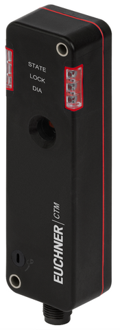
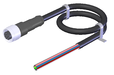
Safety switch with guard locking CTM-LBI-BR BiState, RFID, plug connector(s) M12
- BiState (bistable guard locking)
- Multicode
- Door position monitoring output/communication OD/C
- Plug connector M12, 8-pin
- Actuating/extraction/retention force: 20/18/5 N
- Auxiliary release
Ismertetés
BiState (bistable guard locking)
The device has a function that prevents
- people from accidentally becoming trapped in the event of a power failure or when the machine is switched off and the safety door is open
- the activated guard locking is deactivated in the event of a power failure.
Multicode evaluation
The system checks whether the actuator type is one that can be recognized by the system (multicode evaluation). The system has a low coding level. Every suitable actuator is recognized by the switch.
Auxiliary release
The auxiliary release on the front allows access to the machine in the event of a malfunction, e.g. a power failure.
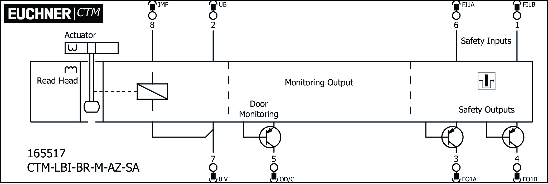
Terminal assignment
| Plug connector (view of connection side) | Pin | Designation | Function | Connecting cable conductor coloring |
|---|---|---|---|---|
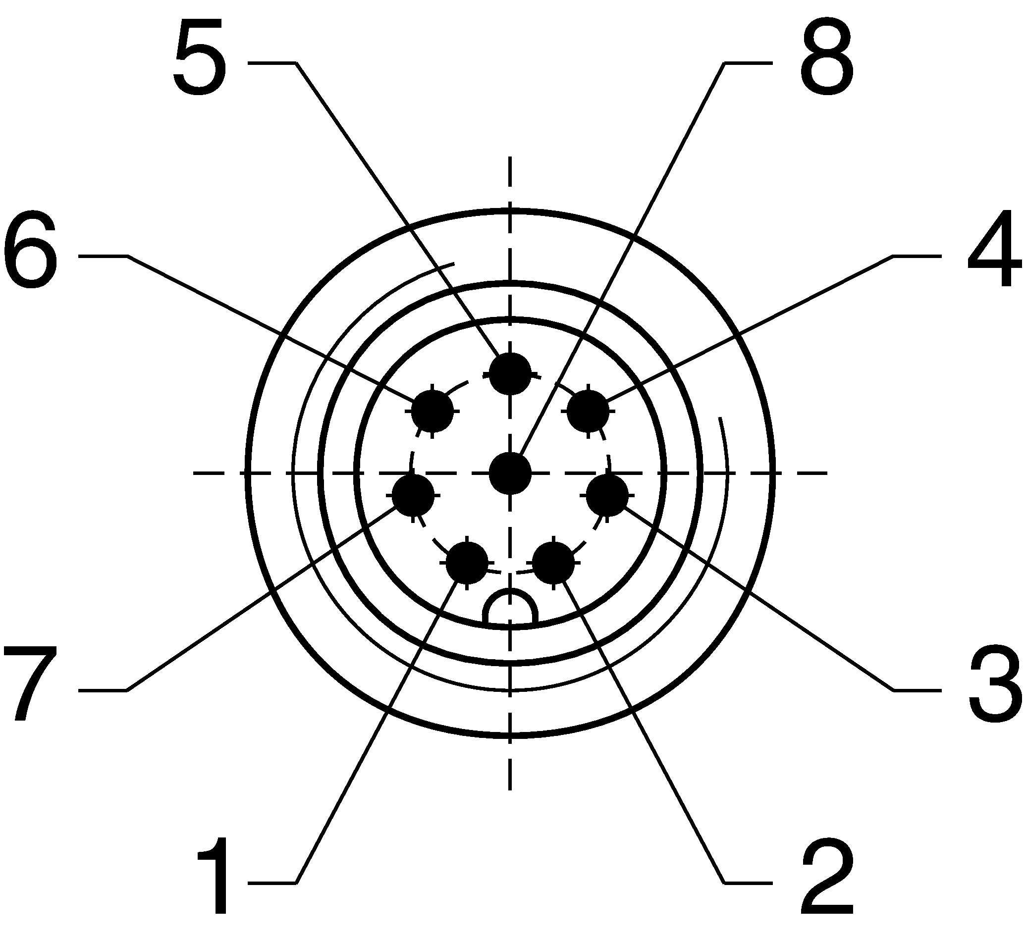 | 1 | FI1B | Enable input, channel B | WH |
| 2 | UB | Operating voltage electronics and magnet 24 V DC | BN | |
| 3 | FO1A | Safety outputs channel A  | GN | |
| 4 | FO1B | Safety outputs channel B | YE | |
| 5 | OD/C | Door position monitoring output/communication | GY | |
| 6 | FI1A | Enable input, channel A | PK | |
| 7 | 0VUB | Electronics and solenoid operating voltage, 0 V DC | BU | |
| 8 | IMP | Solenoid control input, 24 V DC | RD |
Accessories required
Actuator is not included.
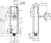
Dimensional drawings
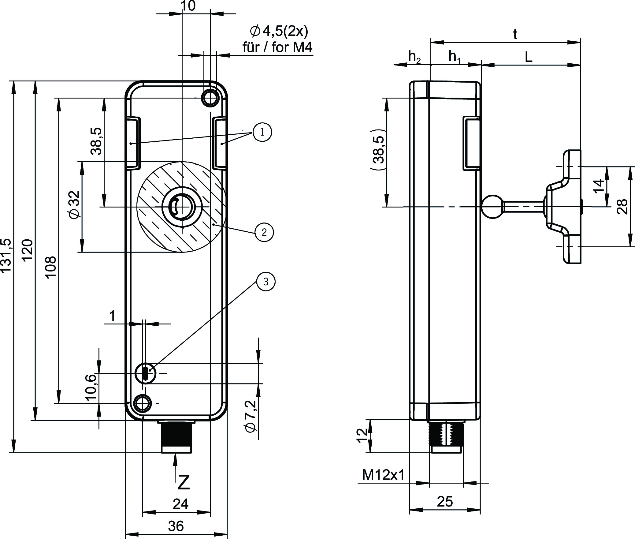
| 1 | LEDs |
| 2 | Active read head face |
| 3 | Auxiliary release |
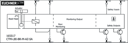
Connection examples
Műszaki adatok
Approvals


Workspace
| Repeat accuracy R | 10 % |
Electrical connection values
| Fuse | |
| external (operating voltage UB) | 0.7 ... 8 A |
| Power consumption | |
| at max. switching frequency | 3 W |
| Rated insulation voltage Ui | 50 V |
| Rated impulse voltage Uimp | 0.5 kV |
| Discrepancy time | |
| both safety outputs | max. 10 ms Acc. to EN IEC 60947-5-3 |
| Turn-on time | max. 400 ms |
| Solenoid duty cycle | 100 % |
| Off-state current Ir | max. 0.25 mA |
| Risk time according to EN 60947-5-3 | max. 200 ms |
| Risk time according to EN 60947-5-3, extension for each additional device | max. 10 ms |
| Switching load | DC 24V, UL Class 2 (alternatively, see operating instructions) |
| Safety class | III |
| Test pulse duration | max. 0.3 ms |
| Test pulse interval | 100 ms |
| Degree of contamination (external, according to EN 60947-1) | 3 |
| Solenoid IMP | |
| Input voltage | |
| Guard locking active (closed) | 0 ... 5 V DC |
| Guard locking not active (open) | 20.4 ... 26.4 V DC |
| Current consumption | |
| Guard locking not active (open) | 20 ... 50 mA |
| Monitoring output OD/C | |
| Output type | p-switching, short circuit-proof |
| Output voltage | 0.8xUB ... UB V DC |
| Switching current | 1 ... 50 mA |
| Safety input 1 | |
| Current consumption | max. 7 mA Safety inputs Fl1A/Fl1B |
| Safety outputs FO1A/FO1B | |
| Output type | 2 semiconductor outputs, p-switching, short circuit-proof |
| Output voltage | |
| LOW U(FO1A) / U(FO1B) | 0 ... 1 V DC |
| HIGH U(FO1A) / U(FO1B) | UB-1.5 ... UB V DC |
| Discrepancy time | Acc. to EN IEC 60947-5-3 |
| Utilization category | |
| DC-13 | 24V 150mA (Caution: outputs must be protected with a free-wheeling diode in case of inductive loads) |
| Electrical switching frequency | max. 0.25 Hz |
| Switching current | |
| per safety output FO1A / FO1B | 1 ... 150 mA |
| Operating voltage UB | |
| Operating voltage DC | |
| UUB | 24 V DC -15% ... +15% reverse polarity protected, regulated, residual ripple<5%, PELV |
| Current consumption | |
| IUB at operating voltage UB = 24 V | max. 500 mA |
Mechanical values and environment
| Anfahrgeschwindigkeit | max. 20 m/min |
| Connection type | Plug connector M12, 8-pin |
| Extraction force | 18 N |
| Ready delay | 5.5 s |
| Actuating force | 20 N |
| Installation orientation | any |
| Switching frequency | max. 0.25 Hz |
| Storage temperature | -25 ... 70 °C |
| Mechanical life | 1 x 10⁶ |
| Overtravel | 2 mm |
| Retention force | 5 N |
| Shock and vibration resistance | Acc. to EN IEC 60947-5-3 |
| Degree of protection | IP65/IP67 (In the inserted and screwed tight state) |
| Ambient temperature | |
| at UB = 24 V DC | -20 ... 60 °C |
| Material | |
| Safety switch housing | Reinforced thermoplastic |
| Seals | Fluorinated rubber (FKM) |
| Locking force Fmax | 1300 N |
| Locking force FZh | 1000 N |
| Guard locking principle | BiState |
Characteristic values according to EN ISO 13849-1 and EN IEC 62061
| PL | Maximum SIL | PFHD | Category | Mission time | |
|---|---|---|---|---|---|
| Control of guard locking | PL d | 2 | 1.03x10⁻⁷ | 3 | 20 y |
| Guard lock monitoring | PL e | 3 | 4.11x10⁻⁹ | 4 | 20 y |
Miscellaneous
| Notices for UL approval | Operation only with UL Class 2 power supply or equivalent measures; see operating instructions |
Tartozékok


Connection material

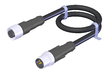


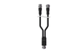
Y-distributor M12 with connection cable, connecting cable
111696
AC-YD-V0,2-SBB-111696
AC-YD-V0,2-SBB-111696
- For the series connection of AR/BR safety switches in switch chains
- Y-distributor M12 with connecting cable, 2 x 5-pin, 1 x 8-pin
- Straight plug connector
- PVC cable
- Cable length 0.2 m
112395
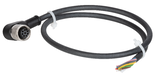
AC-YD-V1,0-SBB-112395
AC-YD-V1,0-SBB-112395
- For the series connection of AR/BR safety switches in switch chains
- Y-distributor M12 with connecting cable, 2 x 5-pin, 1 x 8-pin
- Straight plug connector
- PVC cable
- Cable length 1 m
Letöltések
Teljes csomag
Minden fontos dokumentum letöltése egyetlen kattintással.
Tartalom:
- A használati utasítás és a használati utasítás vagy a rövid utasítás kiegészítései
- A használati utasítást kiegészítő adatlapok
- A megfelelőségi nyilatkozat
Teljes csomag letöltése (ZIP, 5,6 MB)
Egyedi dokumentumok

Declarations of conformity
EU-Konformitätserklärung

Dok. sz.
Változat
Nyelv
Méret
EU-Konformitätserklärung
Dok. sz.
EDC2525461
Változat
Nyelv
Méret
0,5 MB
UKCA-Konformitätserklärung

Dok. sz.
Változat
Nyelv
Méret
UKCA-Konformitätserklärung
Dok. sz.
EDC20001477
Változat
Nyelv
Méret
0,1 MB
Instructions
Operating Instructions Transponder-Coded Safety Switch with Guard Locking CTM-LBI-BP/BR Unicode/Multicode with control of guard locking via control input IMP


Dok. sz.
Változat
Nyelv
Méret
Operating Instructions Transponder-Coded Safety Switch with Guard Locking CTM-LBI-BP/BR Unicode/Multicode with control of guard locking via control input IMP
Dok. sz.
2525462
Változat
10/24
Nyelv
Méret
2,8 MB
Mode d’emploi Interrupteur de sécurité à codage par transpondeur avec interverrouillage CTM-LBI-BP/BR Uni-/multicode avec commande de l’interverrouillage via l’entrée de commande IMP
Dok. sz.
2525462
Változat
10/24
Nyelv
Méret
2,8 MB
Manual de instrucciones Interruptor de seguridad codificado por transponder con bloqueo CTM-LBI-BP/BR Unicode/Multicode con accionamiento del bloqueo a través de la entrada de control IMP
Dok. sz.
2525462
Változat
10/24
Nyelv
Méret
2,8 MB
Betriebsanleitung Transpondercodierter Sicherheitsschalter mit Zuhaltung CTM-LBI-BP/BR Uni-/Multicode mit Ansteuerung der Zuhaltung über den Steuereingang IMP
Dok. sz.
2525462
Változat
10/24
Nyelv
Méret
2,8 MB
Návod k použití Bezpečnostní spínač s kódovaným transpondérem a jištěním ochranného krytu CTM-LBI-BP/BR Unicode/Multicode s ovládáním jištění ochranného krytu prostřednictvím řídicího vstupu IMP
Dok. sz.
2525462
Változat
10/24
Nyelv
Méret
2,9 MB

Egyéb dokumentumok
Approvals and certificates
FCC

Dok. sz.
Változat
Nyelv
Méret
FCC
Dok. sz.
Változat
Nyelv
Méret
0,1 MB
ISED

Dok. sz.
Változat
Nyelv
Méret
ISED
Dok. sz.
Változat
Nyelv
Méret
1,2 MB
Information EU Data Act

Dok. sz.
Változat
Nyelv
Méret
Information EU Data Act
Dok. sz.
ECO20001824
Változat
Nyelv
Méret
0,1 MB
UQS CTM…BI…

Dok. sz.
Változat
Nyelv
Méret
UQS CTM…BI…
Dok. sz.
ECO20001463
Változat
Nyelv
Méret
0,2 MB
WEEE

Dok. sz.
Változat
Nyelv
Méret
WEEE
Dok. sz.
ECO20001806
Változat
Nyelv
Méret
0,1 MB
c UL us

Dok. sz.
Változat
Nyelv
Méret
c UL us
Dok. sz.
Változat
Nyelv
Méret
0,3 MB
Sales documents


Rendelési adatok
| Rend. sz. | 165517 |
| Cikk neve | CTM-LBI-BR-M-AZ-SA-165517 |
| Súly | 0,26kg |
| Vámtarifaszám | 85365019 |
| ECLASS | 27-27-24-05 Safety-related transponder switch with guardlocking |