CTS-C1-BP-CC-FLX-AP-VBB-172474 (Rend. sz. 172474)
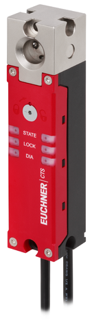
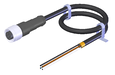
Safety switch with guard locking CTS-C1-BP FlexFunction, RFID, connection cable PVC with plug connector(s) M12, for connection to decentralized peripheral system
- Closed-circuit current principle
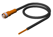
- Connection cable, connecting cable PVC, 25 cm, 2 x plug connector(s) M12, 5-pin
- for connection to decentralized peripheral systems
Ismertetés
Direct connection to decentralized peripheral systems
The connection via M12 plug connector(s) is optimized for direct connection to IP67 IO modules, such as ET200pro and ET200eco from SIEMENS, MVK from MURR and EP1957 from BECKHOFF.
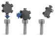
FlexFunction
The switch is configured by the function actuator during setup. Depending on the selection of the function actuator, the guard lock monitoring of the safety switch is active or inactive and the evaluation of the actuator code is high-coded or low-coded.
Guard locking principle
Power to unlock: On a guard with guard locking based on the closed-circuit current principle, the guard is locked by spring force until the guard locking solenoid is supplied with power. Unlocking is by solenoid force. The term mechanical guard locking is also used.
Auxiliary release
The auxiliary release on the front and rear sides allows access to the machine in the event of a malfunction, e.g. a power failure.
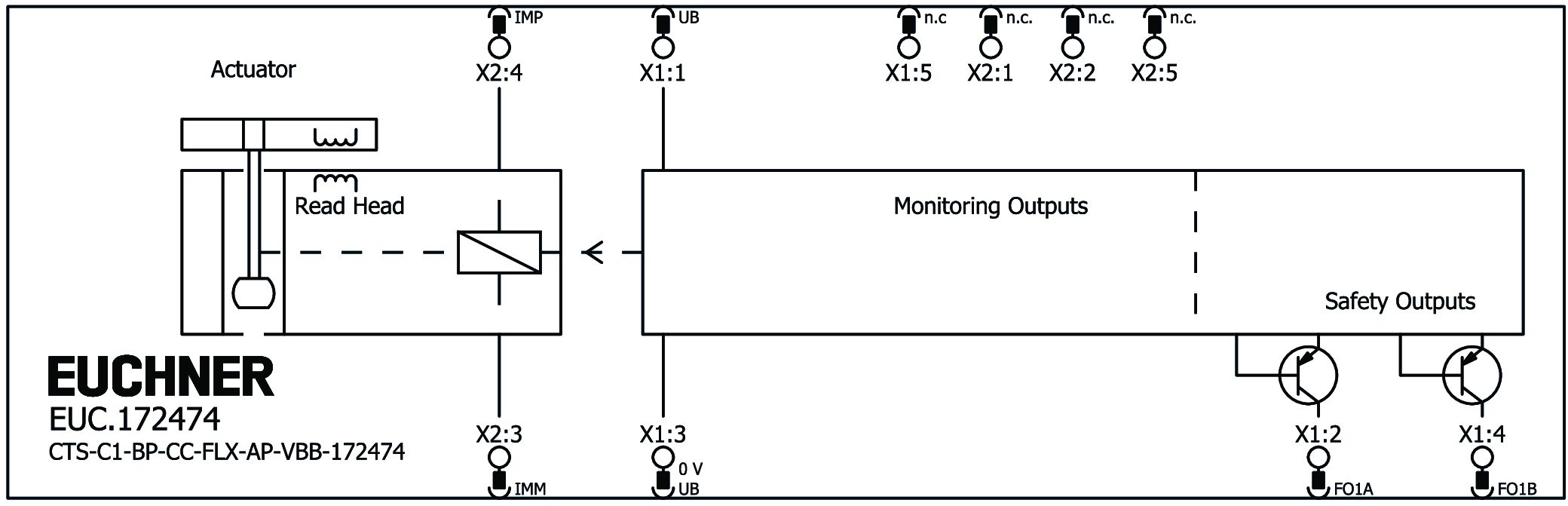
Terminal assignment
| Plug connector (view of connection side) | Pin | Designation | Function | Connecting cable conductor coloring |
|---|---|---|---|---|
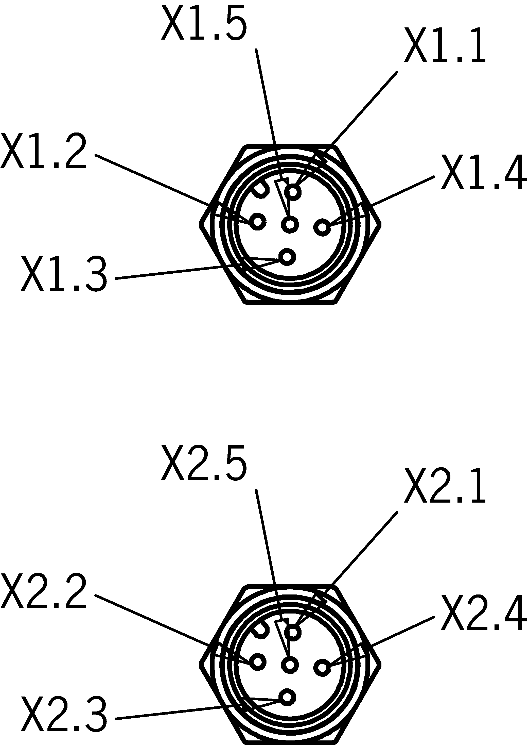 | X 1.1 | UB | Electronics operating voltage, 24 V DC | BN |
| X 1.2 | FO1A | Safety output, channel A | WH | |
| X 1.3 | 0 V UB | Electronics operating voltage, 0 V DC | BU | |
| X 1.4 | FO1B | Safety output, channel B | BK | |
| X 1.5 | - | n.c. | GY | |
| X 2.1 | - | n.c. | BN | |
| X 2.2 | - | n.c. | WH | |
| X 2.3 | IMM | Solenoid operating voltage, 0 V DC | BU | |
| X 2.4 | IMP | Solenoid operating voltage, 24 V DC | BK | |
| X 2.5 | - | n.c. | GY |
Pin assignment X1.2 and X1.4 depending on the function actuator
| Pin | A-FLX-D-0C-167919 | A-FLX-D-0D-169044 | A-FLX-D-0E-169045 | A-FLX-D-0F-169046 |
|---|---|---|---|---|
| L + HC | I + HC | L + LC | I + LC | |
| X1.2 |  | | ||
| X1.4 | | |
Accessories required
Actuator is not included.
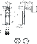
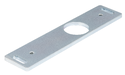
Dimensional drawings
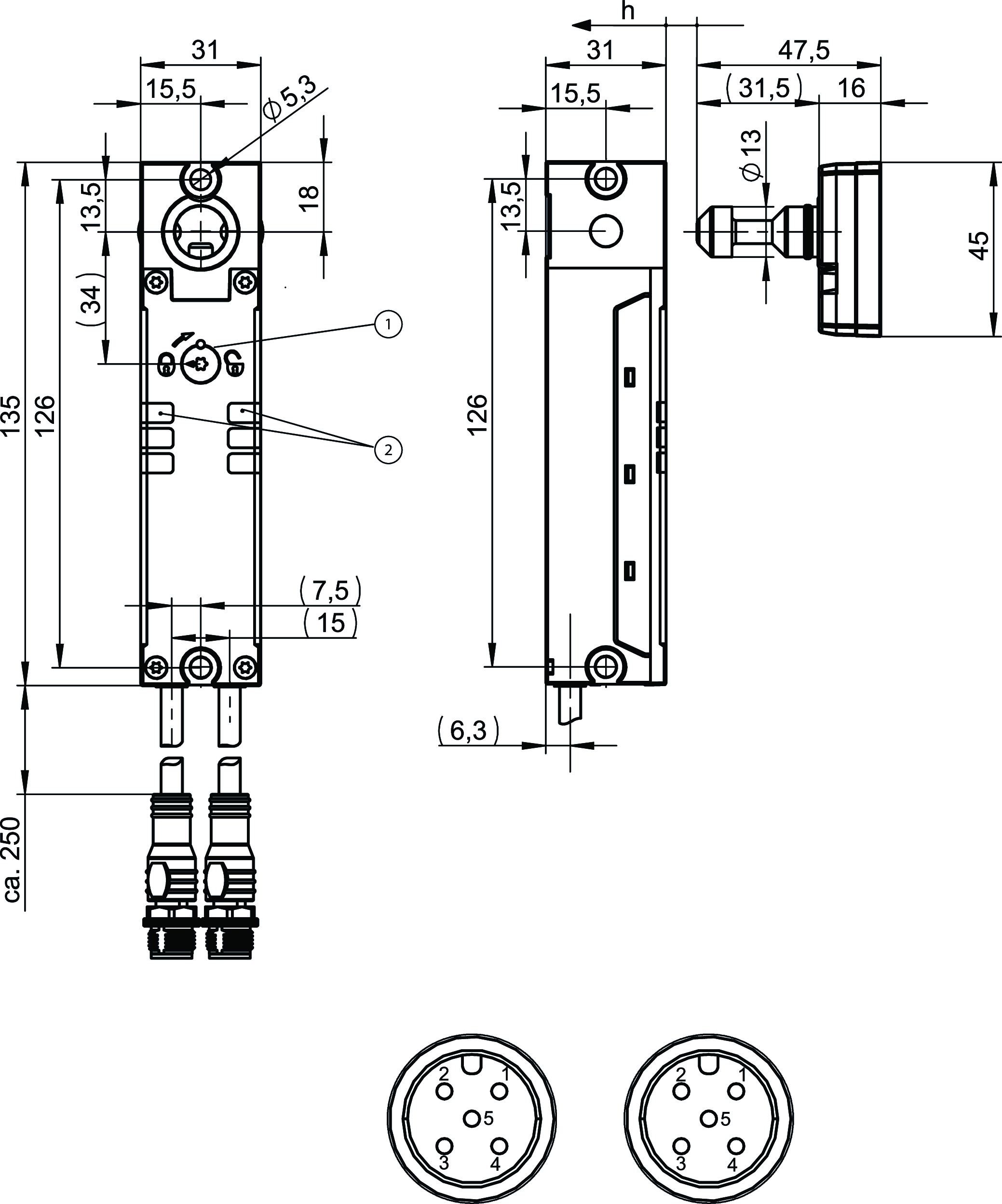
| 1 | Auxiliary release |
| 2 | LEDs |
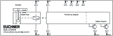
Connection examples
Műszaki adatok
Approvals


Electrical connection values
| Fuse | |
| IMP | 1 ... 8 A external |
| UB | 1 ... 8 A external |
| Power consumption | 9 W |
| rated conditional short-circuit current | 100 A |
| Rated insulation voltage Ui | 32 V |
| Rated impulse voltage Uimp | 0.8 kV |
| Operating voltage DC | |
| UB | 24 V DC -15% ... +20% (reverse polarity protected, regulated, residual ripple<5%, SELV) |
| Discrepancy time | max. 10 ms |
| Turn-on time | max. 400 ms |
| EMC protection requirements | Acc. to EN IEC 60947-5-3 |
| Solenoid operating voltage DC | 24 V DC -15% ... +20% reverse polarity protected, regulated, residual ripple<5%, SELV |
| Solenoid duty cycle | 100 % |
| Risk time according to EN 60947-5-3 | max. 200 ms |
| Risk time according to EN 60947-5-3, extension for each additional device | max. 10 ms |
| Switching load | |
| according to UL | DC 24 V, Class 2 |
| Safety class | III |
| Current consumption | |
| IIMP | 500 mA |
| IUB | 50 mA |
| Degree of contamination (external, according to EN 60947-1) | 3 |
| Safety outputs FO1A/FO1B | |
| Output type | Semiconductor outputs, p-switching, short circuit-proof |
| Output voltage | |
| UFO1A /UFO1B LOW | 0 ... 1 V DC |
| UFO1A /UFO1B HIGH | UB-4V ... UB V DC (Value at a switching current of 50mA without taking into account the cable lengths) |
| Output current | |
| L configuration (guard lock monitoring active) | 1 ... 80 mA |
| I-configuration (guard lock monitoring inactive) | 1 ... 75 mA |
| Utilization category | |
| DC-13 L configuration (guard lock monitoring active) | 24V 80mA (Caution: outputs must be protected with a free-wheeling diode in case of inductive loads) |
| DC-13 I configuration (guard lock monitoring inactive) | 24V 75mA (Caution: outputs must be protected with a free-wheeling diode in case of inductive loads) |
| Test pulse duration | max. 0.3 ms |
| Test pulse interval | min. 96 ms |
Mechanical values and environment
| Anfahrgeschwindigkeit | max. 20 m/min |
| Extraction force | 25 N |
| Ready delay | max. 1 s |
| Actuating force | 25 N |
| Installation orientation | any |
| Storage temperature | -25 ... 70 °C |
| Mechanical life | 1 x 10⁶ |
| Retention force | 10 N |
| Shock and vibration resistance | Acc. to EN IEC 60947-5-3 |
| Degree of protection | IP65/IP67/IP69/IP69K |
| Ambient temperature | -20 ... 55 °C (A maximum value of +50 °C applies in the I-configuration of the switch (guard lock monitoring inactive)) |
| Material | |
| Safety switch housing | Reinforced thermoplastic |
| Switch head cover | Die-cast zinc |
| Connecting cable | PVC |
| Locking force Fmax | 5000 N |
| Locking force FZh | 3800 N |
| Guard locking principle | Closed-circuit current principle |
| Connection X1/X2 | |
| Connection type | Connecting cable with plug connector M12 |
| Static bending radius | 8x cable diameter |
| Cable outlet | straight |
| Cable length | 0.25 m |
| Number of pins | 5 |
| Safety outputs FO1A/FO1B | |
| Switching frequency | max. 0.2 Hz |
Characteristic values according to EN ISO 13849-1 and EN IEC 62061
| PL | Maximum SIL | PFHD | Category | Mission time | |
|---|---|---|---|---|---|
| Monitoring of the guard position | PL e | 3 | 6.44x10⁻⁹ | 4 | 20 y |
| Guard lock monitoring | PL e | 3 | 6.44x10⁻⁹ | 4 | 20 y |
| Applies only if guard lock monitoring is active (guard locking for protection of personnel). Dependent on the actuator used. | |||||
| PL | Maximum SIL | Category | Mission time | |
|---|---|---|---|---|
| Control of guard locking | Depending on external control of guard locking | 20 y | ||
Miscellaneous
| Notices for UL approval | Operation only with UL Class 2 power supply or equivalent measures; see operating instructions |
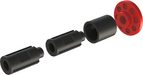
Tartozékok

A-FLX-D-0C-167919
- Function actuator for configuration of the safety switch CTS
- Configuration: monitoring of the guard locking, high coding level (L+HC)

A-FLX-D-0D-169044
- Function actuator for configuration of the safety switch CTS
- Configuration: monitoring of the door position, high coding level (I+HC)

A-FLX-D-0E-169045
- Function actuator for configuration of the safety switch CTS
- Configuration: monitoring of the guard locking, low coding level (L+LC)

A-FLX-D-0F-169046
- Function actuator for configuration of the safety switch CTS
- Configuration: monitoring of the door position, low coding level (I+LC)

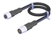
C-M12F05-05X034PU01,5-M12M05-159356
- M12 female plug to M12 plug connector, 5-pin
- Straight female plug and plug connector
- Connecting cable according to AIDA standard
- PUR cable, sheath color gray
- Cable length 1.5 m

C-M12F05-05X034PU01,5-M12M05-159363
- M12 female plug to M12 plug connector, 5-pin
- Straight female plug and plug connector
- Connecting cable according to AIDA standard
- PUR cable, sheath color yellow
- Cable length 1.5 m
C-M12F05-05X034PU10,0-M12M05-119947
- M12 female plug to M12 plug connector, 5-pin
- Straight female plug and plug connector
- PUR cable
- Cable length 10 m
C-M12F05-05X034PV10,0-M12M05-100181
- M12 female plug to M12 plug connector, 5-pin
- Straight female plug and plug connector
- PVC cable
- Cable length 10 m
C-M12F05-05X034PU10,0-M12M05-159360
- M12 female plug to M12 plug connector, 5-pin
- Straight female plug and plug connector
- Connecting cable according to AIDA standard
- PUR cable, sheath color gray
- Cable length 10 m
C-M12F05-05X034PU10,0-M12M05-159920
- M12 female plug to M12 plug connector, 5-pin
- Straight female plug and plug connector
- Connecting cable according to AIDA standard
- PUR cable, sheath color yellow
- Cable length 10 m
C-M12F05-05X034PU15,0-M12M05-159361
- M12 female plug to M12 plug connector, 5-pin
- Straight female plug and plug connector
- Connecting cable according to AIDA standard
- PUR cable, sheath color gray
- Cable length 15 m
C-M12F05-05X034PU15,0-M12M05-159921
- M12 female plug to M12 plug connector, 5-pin
- Straight female plug and plug connector
- Connecting cable according to AIDA standard
- PUR cable, sheath color yellow
- Cable length 15 m
C-M12F05-05X034PU01,0-M12M05-159355
- M12 female plug to M12 plug connector, 5-pin
- Straight female plug and plug connector
- Connecting cable according to AIDA standard
- PUR cable, sheath color gray
- Cable length 1 m
C-M12F05-05X034PU01,0-M12M05-159362
- M12 female plug to M12 plug connector, 5-pin
- Straight female plug and plug connector
- Connecting cable according to AIDA standard
- PUR cable, sheath color yellow
- Cable length 1 m
C-M12F05-05X034PU20,0-M12M05-119971
- M12 female plug to M12 plug connector, 5-pin
- Straight female plug and plug connector
- PUR cable
- Cable length 20 m
C-M12F05-05X034PV20,0-M12M05-100182
- M12 female plug to M12 plug connector, 5-pin
- Straight female plug and plug connector
- PVC cable
- Cable length 20 m
C-M12F05-05X034PU03,0-M12M05-159357
- M12 female plug to M12 plug connector, 5-pin
- Straight female plug and plug connector
- Connecting cable according to AIDA standard
- PUR cable, sheath color gray
- Cable length 3 m
C-M12F05-05X034PU03,0-M12M05-159364
- M12 female plug to M12 plug connector, 5-pin
- Straight female plug and plug connector
- Connecting cable according to AIDA standard
- PUR cable, sheath color yellow
- Cable length 3 m
C-M12F05-05X034PU05,0-M12M05-119932
- M12 female plug to M12 plug connector, 5-pin
- Straight female plug and plug connector
- PUR cable
- Cable length 5 m
C-M12F05-05X034PV05,0-M12M05-100180
- M12 female plug to M12 plug connector, 5-pin
- Straight female plug and plug connector
- PVC cable
- Cable length 5 m
C-M12F05-05X034PU05,0-M12M05-159358
- M12 female plug to M12 plug connector, 5-pin
- Straight female plug and plug connector
- Connecting cable according to AIDA standard
- PUR cable, sheath color gray
- Cable length 5 m
C-M12F05-05X034PU05,0-M12M05-159365
- M12 female plug to M12 plug connector, 5-pin
- Straight female plug and plug connector
- Connecting cable according to AIDA standard
- PUR cable, sheath color yellow
- Cable length 5 m
C-M12F05-05X034PU08,0-M12M05-159359
- M12 female plug to M12 plug connector, 5-pin
- Straight female plug and plug connector
- Connecting cable according to AIDA standard
- PUR cable, sheath color gray
- Cable length 8 m
C-M12F05-05X034PU08,0-M12M05-159919
- M12 female plug to M12 plug connector, 5-pin
- Straight female plug and plug connector
- Connecting cable according to AIDA standard
- PUR cable, sheath color yellow
- Cable length 8 m


Letöltések
Teljes csomag
Minden fontos dokumentum letöltése egyetlen kattintással.
Tartalom:
- A használati utasítás és a használati utasítás vagy a rövid utasítás kiegészítései
- A használati utasítást kiegészítő adatlapok
- A megfelelőségi nyilatkozat
Egyedi dokumentumok


Egyéb dokumentumok


Rendelési adatok
| Rend. sz. | 172474 |
| Cikk neve | CTS-C1-BP-CC-FLX-AP-VBB-172474 |
| Súly | 0,595kg |
| Vámtarifaszám | 85365019000 |
| ECLASS | 27-27-24-05 Safety-related transponder switch with guardlocking |