CTM-L2-BR-M-ZZ-V15-P-173223 (Rend. sz. 173223)
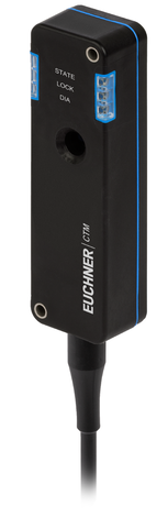
Safety switch with guard locking CTM-L2-BR, RFID, connection cable, connecting cable PVC, hygienic version
- Open-circuit current principle
- Guard locking for process protection
- Multicode
- Door position monitoring output/communication OD/C
- Connection cable, connecting cable PVC, 15m, flying lead
- Actuating/extraction/retention force: 35/30/15 N
- Hygienic version
Ismertetés
Guard locking principle
Open-circuit current (power on to lock): On a guard with guard locking based on the open-circuit current principle, the guard is locked until the power supply to the guard locking solenoid is interrupted. Unlocking is by spring force. The term electrical guard locking is also used.
Guard locking for process protection
The safety switch meets the requirements for interlocking devices with guard locking for process protection. It does not possess safe guard lock monitoring.
Switching function
The safety outputs are switched on when guard locking is active.
Multicode evaluation
The system checks whether the actuator type is one that can be recognized by the system (multicode evaluation). The system has a low coding level. Every suitable actuator is recognized by the switch.
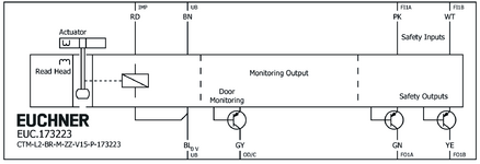
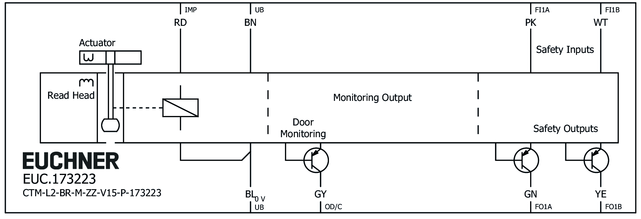
Terminal assignment
| Designation | Function | Connecting cable conductor coloring |
|---|---|---|
| FI1B | Enable input, channel B | WH |
| UB | Electronics and solenoid operating voltage, 24 V DC | BN |
| FO1A | Safety output, channel A | GN |
| FO1B | Safety output, channel B | YE |
| OD/C | Door position monitoring output/communication | GY |
| FI1A | Enable input, channel A | PK |
| 0VUB | Electronics and solenoid operating voltage, 0 V DC | BU |
| IMP | Solenoid control input, 24 V DC | RD |
Accessories required
Actuator is not included.
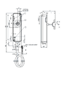
Dimensional drawings
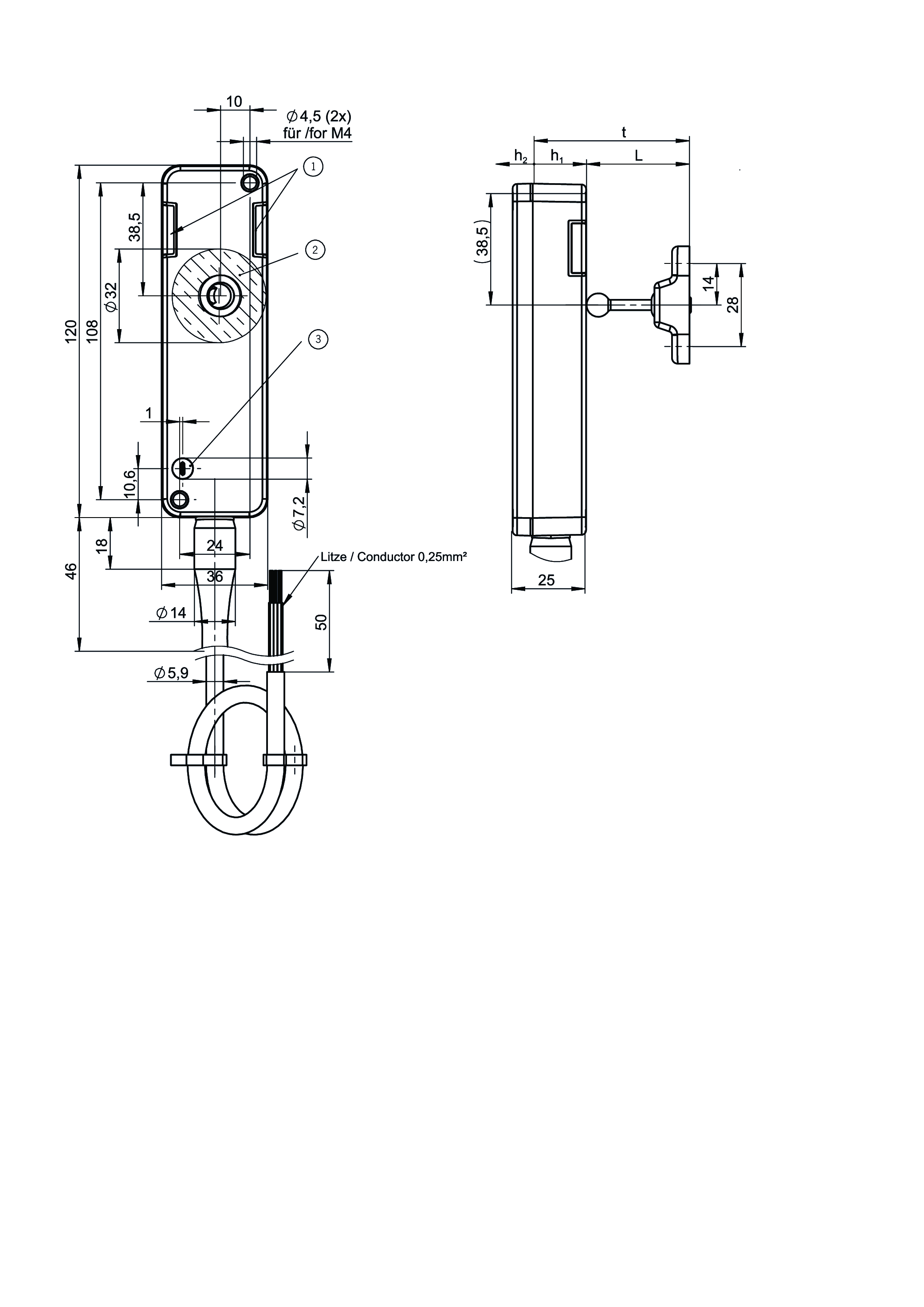
| 1 | LEDs |
| 2 | Active read head face |
| 3 | Auxiliary release (optional) |
Connection examples
Műszaki adatok
Approvals


Workspace
| Repeat accuracy R | 10 % |
Electrical connection values
| Fuse | |
| external (operating voltage UB) | 0.7 ... 8 A |
| Power consumption | |
| at max. switching frequency | 3 W |
| Rated insulation voltage Ui | 50 V |
| Rated impulse voltage Uimp | 0.5 kV |
| Discrepancy time | |
| both safety outputs | max. 10 ms Acc. to EN IEC 60947-5-3 |
| Turn-on time | max. 500 ms |
| Solenoid duty cycle | 100 % |
| Off-state current Ir | max. 0.25 mA |
| Risk time according to EN 60947-5-3 | max. 200 ms |
| Risk time according to EN 60947-5-3, extension for each additional device | max. 10 ms |
| Switching load | DC 24V, UL Class 2 (alternatively, see operating instructions) |
| Safety class | III |
| Test pulse duration | max. 0.3 ms |
| Test pulse interval | 100 ms |
| Degree of contamination (external, according to EN 60947-1) | 3 |
| Solenoid IMP | |
| Input voltage | |
| Guard locking active (closed) | 20.4 ... 26.4 V DC |
| Guard locking not active (open) | 0 ... 5 V DC |
| Current consumption | |
| Guard locking active (closed) | 20 ... 50 mA |
| Door position monitoring output/communication OD/C | |
| Output type | p-switching, short circuit-proof |
| Output voltage | 0.8xUB ... UB V DC |
| Switching current | 1 ... 50 mA |
| Safety input | |
| Current consumption | max. 7 mA Safety inputs Fl1A/Fl1B |
| Safety outputs FO1A/FO1B | |
| Output type | 2 semiconductor outputs, p-switching, short circuit-proof |
| Output voltage | |
| HIGH U(FO1A) / U(FO1B) | UB-1.5 ... UB V DC |
| LOW U(FO1A) / U(FO1B) | 0 ... 1 V DC |
| Discrepancy time | Acc. to EN IEC 60947-5-3 |
| Utilization category | |
| DC-13 | 24V 150mA (Caution: outputs must be protected with a free-wheeling diode in case of inductive loads) |
| Electrical switching frequency | max. 0.25 Hz |
| Switching current | |
| per safety output FO1A / FO1B | 1 ... 150 mA |
| Operating voltage UB | |
| Operating voltage DC | |
| UUB | 24 V DC -15% ... +15% reverse polarity protected, regulated, residual ripple<5%, PELV |
| Current consumption | |
| IUB at operating voltage UB = 24 V | max. 500 mA |
Mechanical values and environment
| Anfahrgeschwindigkeit | max. 20 m/min |
| Connection type | Connecting cable (screwed tight, plug connector/mating component. Please observe the notes in the operating instructions when using high-pressure cleaners.) |
| Extraction force | 30 N |
| Ready delay | 5.5 s |
| Actuating force | 35 N |
| Installation orientation | any |
| Switching frequency | max. 0.25 Hz |
| Storage temperature | -25 ... 70 °C |
| Mechanical life | 1 x 10⁶ |
| Overtravel | 2 mm |
| Retention force | 15 N |
| Shock and vibration resistance | Acc. to EN IEC 60947-5-3 |
| Degree of protection | IP65/IP67/IP69/IP69K (In the inserted and screwed tight state) |
| Ambient temperature | |
| at UB = 24 V DC | -20 ... 60 °C |
| Material | |
| Safety switch housing | Reinforced thermoplastic |
| Encapsulation | Technomelt PA6208 black |
| Cable sheath | PVC |
| Seals | Fluorinated rubber (FKM) |
| Locking force Fmax | 1300 N |
| Locking force FZh | 1000 N |
| Guard locking principle | Open-circuit current principle |
Characteristic values according to EN ISO 13849-1 and EN IEC 62061
| PL | Maximum SIL | PFHD | Category | Mission time | |
|---|---|---|---|---|---|
| Monitoring of the guard position | PL e | 3 | 4.11x10⁻⁹ | 4 | 20 y |
Miscellaneous
| Notices for UL approval | Operation only with UL Class 2 power supply or equivalent measures; see operating instructions |


Letöltések
Teljes csomag
Minden fontos dokumentum letöltése egyetlen kattintással.
Tartalom:
- A használati utasítás és a használati utasítás vagy a rövid utasítás kiegészítései
- A használati utasítást kiegészítő adatlapok
- A megfelelőségi nyilatkozat
Egyedi dokumentumok


Egyéb dokumentumok


Rendelési adatok
| Rend. sz. | 173223 |
| Cikk neve | CTM-L2-BR-M-ZZ-V15-P-173223 |
| Súly | 1,03kg |
| Vámtarifaszám | 85365019000 |
| ECLASS | 27-27-24-05 Safety-related transponder switch with guardlocking |