STP-TW-4A-4141AC024SEM4AS1 (Rend. sz. 109813)
Safety switch STP TWIN ASi, plug connector M12
- AS-Interface
- TWIN function (two actuating heads)
- Plug connector M12, 4-pin
- Auxiliary release
- Open-circuit current principle

Ismertetés
Version TWIN
The switch has two actuating heads. They enable two movable guards to be secured at the same time.
Approach direction

Horizontal and vertical
Can be adjusted in 90° steps
Increased overtravel for horizontal approach direction
If increased play is required when the door is closed, an actuator with overtravel is available. With this actuator the door can move slightly in the actuating direction when closed. This is important, for example, if safety doors have a rubber end stop. Using an actuator with overtravel, the continuous pressure from the compressed rubber can be reduced. In this way the load is reduced on the switch head and the door mechanism.
Guard locking principle
Power to unlock: On a guard with guard locking based on the closed-circuit current principle, the guard is locked by spring force until the guard locking solenoid is supplied with power. Unlocking is by solenoid force. The term mechanical guard locking is also used.
Control of the guard locking solenoid
The guard locking solenoid is controlled via AS-Interface bit D0. In order to achieve safe control of the guard locking, the auxiliary voltage must also be switched safely.
Auxiliary voltage
The ASi auxiliary voltage is required to supply the guard locking solenoid.
AS-Interface inputs
D0, D1 | Monitoring of the guard position |
D2, D3 | Guard lock monitoring |
AS-Interface outputs
D0 | Control of guard locking |
D1 | LED red |
D2 | LED green |
LED indicator
The Power LED indicates the operating voltage on the bus.
The Fault LED indicates if a fault has been detected on the AS-Interface bus.
The green and the red LEDs can be controlled as required by the control system via the bus using bits D1 and D2.
Auxiliary release
The auxiliary release on the front makes it possible to access the machine if there is a malfunction, e.g. a power failure. Unlocking is performed using a tool or a key. The auxiliary release must be protected against misuse (sealing, lacquer).
Accessories required
Actuator is not included.
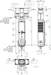
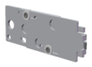
Dimensional drawings
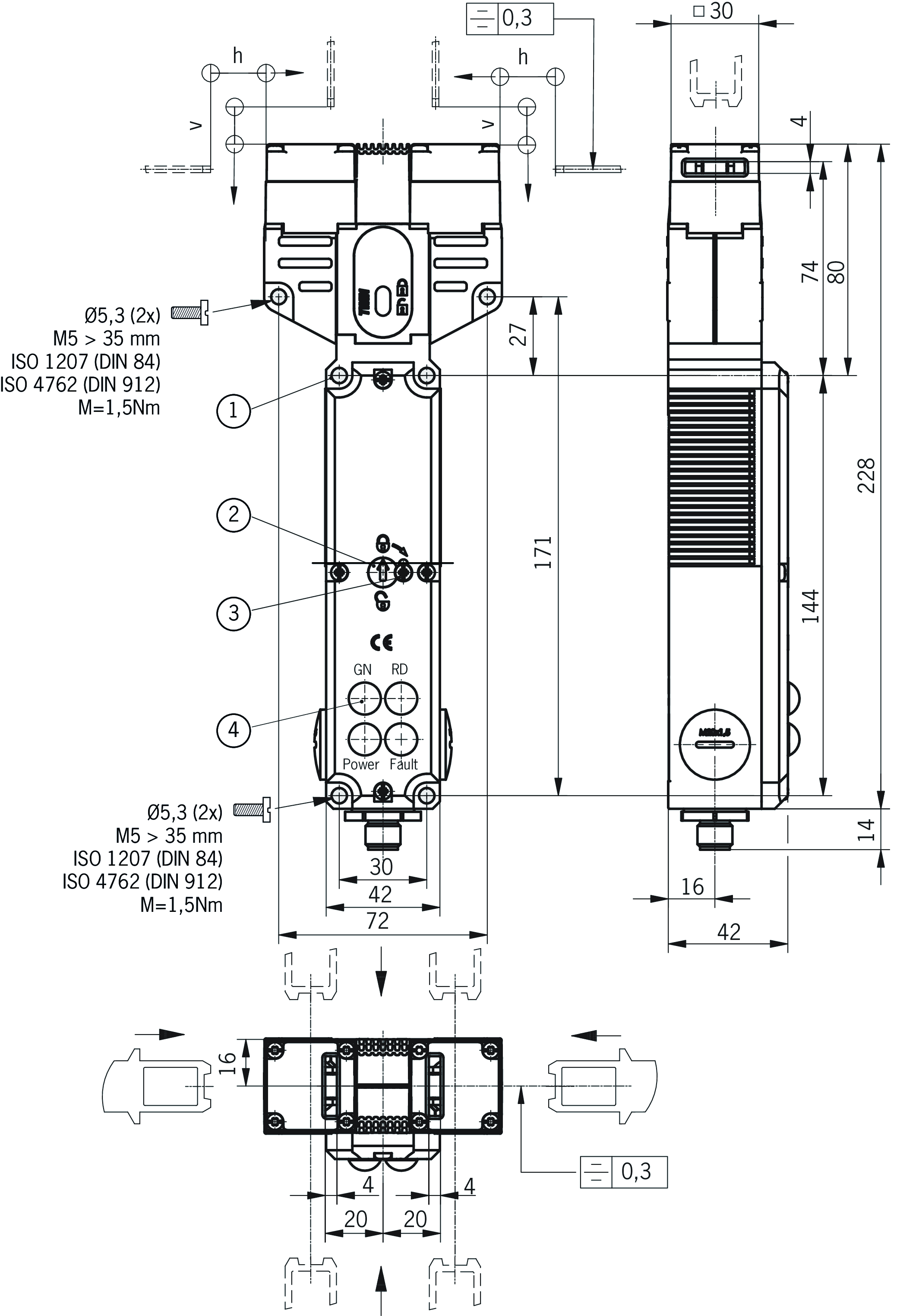
| 1 | Do not screw tight here (2x) |
| 2 | Auxiliary release |
| 3 | Locking screw |
| 4 | LED indicator |
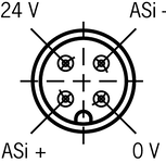
Connection examples

| View of plug side |
Műszaki adatok
Approvals


Electrical connection values
| ASI operating current | max. 45 mA |
| AS-Interface auxiliary voltage | 20.4 ... 24 ... 26.4 V |
| Auxiliary current AS-Interface | 300 mA |
| AS-Interface LED | |
| green | Power |
| red | Fault |
| AS-Interface protocol | ASi-3 |
| ASI data out | D0 = control of guard locking, D1 = red LED, D2 = green LED |
| ASI data in | D0, D1 = door position, D2, D3 = guard locking |
| AS-Interface slave type | ID-Code: B, EA-Code: 7 |
| ASI voltage | 22.5 ... 30 ... 31.6 V |
| Solenoid duty cycle | 100 % |
Mechanical values and environment
| Anfahrgeschwindigkeit | max. 20 m/min |
| Approach direction | A and C (two actuating heads) |
| Connection type | |
| 1 x | Plug connector M12 (4-pin) |
| Number of door position positively driven contacts | |
| according to AS-i Safety at Work | |
| Number of guard lock monitoring positively driven contacts | |
| according to AS-i Safety at Work | D2,D3 (1 = locked) |
| Extraction force | 30 N |
| Actuation frequency | max. 1200 1/h |
| Actuating force | 35 N |
| Installation orientation | any |
| Storage temperature | -25 ... 70 °C |
| Mechanical life | 1 x 10⁶ |
| Retention force | 20 N |
| Switching principle | Slow-action switching contact |
| Degree of protection | IP67 |
| Ambient temperature | -20 ... 55 °C |
| Material | |
| Housing | Reinforced thermoplastic |
| Contact | Silver alloy, gold flashed |
| Locking force Fmax | 2500 N |
| Locking force FZh | 2000 N |
| Guard locking principle | Open-circuit current principle |
Characteristic values according to EN ISO 13849-1 and EN IEC 62061
| B10D | Mission time | |
|---|---|---|
| Guard lock monitoring | 4.5x10⁶ | 20 y |
| Important! Values valid at DC-13 100 mA/24V | ||
In combination with actuator ACTUATOR-S-GT-SN
| Horizontal insertion depth | 24.5 mm |
| Vertical insertion depth | 24.5 mm |
| Horizontal overtravel | 5 mm |
| Vertical overtravel | 5 mm |
Tartozékok


AE-K-A1-DULK1-84177
- Lock unique locking
- Key removable in “unlocked” and “locked” positions

AE-K-A1-ILK1-121917
- Identical locking
- Key removable in “locked” position
AE-K-A1-IUK2-109212
- Identical locking
- Key can be removed only in “unlocked” position
AE-K-A1-IULK1-86236
- Identical locking
- Key removable in “unlocked” and “locked” positions

AE-B-A1-02,0-096230
- Can be used as escape release or emergency release
- no automatic return
- Sheath length 2 m (rope length 6 m)
AE-B-A1-02,0-F-097747
- Can be used as escape release or emergency release
- automatic return
- Sheath length 2 m (rope length 6 m)
AE-B-A1-03,0-098313
- Can be used as escape release or emergency release
- no automatic return
- Sheath length 3 m (rope length 6 m)
AE-B-A1-03,0-F-111233
- Can be used as escape release or emergency release
- automatic return
- Sheath length 3 m (rope length 6 m)
AE-B-A1-04,0-098314
- Can be used as escape release or emergency release
- no automatic return
- Sheath length 4 m (rope length 6 m)
AE-B-A1-06,0-125582
- Can be used as escape release or emergency release
- no automatic return
- Rope length 6 m (without sheath)
AE-B-A1-06,0-F-124770
- Can be used as escape release or emergency release
- automatic return
- Rope length 6 m (without sheath)

Letöltések
Teljes csomag
Minden fontos dokumentum letöltése egyetlen kattintással.
Tartalom:
- A használati utasítás és a használati utasítás vagy a rövid utasítás kiegészítései
- A használati utasítást kiegészítő adatlapok
- A megfelelőségi nyilatkozat
Egyedi dokumentumok


Egyéb dokumentumok


CAD-adatok

Rendelési adatok
| Rend. sz. | 109813 |
| Cikk neve | STP-TW-4A-4141AC024SEM4AS1 |
| Súly | 0,703kg |
| Vámtarifaszám | 85365019000 |
| ECLASS | 27-27-26-03 Safety switch with guard control |