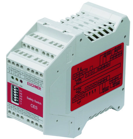
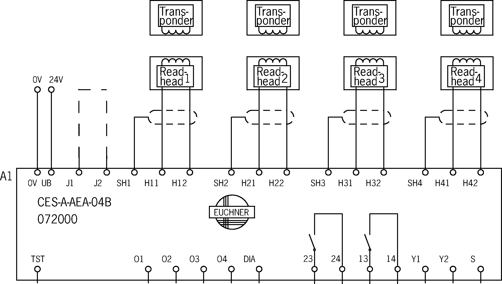
CES-A-AEA-04B (Rend. sz. 072000)
Válasszon tartalmat
Evaluation unit CES-A-AEA-04B/CES-A-UEA-04B (for 4 read heads)
- 4 read heads can be connected
- 2 safety contacts (relay contacts)
- 1 internal normally open contact per safety contact
- Start button and feedback loop can be connected
- Unicode evaluation unit
- Category 4 / PL e according to EN ISO 13849-1
Ismertetés
Unicode evaluation unit
Each actuator is highly coded (unicode). The evaluation unit detects only actuators that have been taught-in. Additional actuators can be taught-in.
Only the last actuator taught-in is detected. New actuators are taught-in by fitting a jumper.
Category according to EN ISO 13849-1
Due to two redundant relay outputs (safety outputs) with internally monitored contacts, suitable for:
- Category 4 / PL e according to EN ISO 13849-1
Actuating range
The evaluation unit has the standard actuating range that, e.g., permits larger tolerances in the alignment of read head and actuator.
TST | Input for self-test |
DIA | Diagnostic output |
O1...O4 | Monitoring outputs (semiconductor) |
Y1,Y2 | Feedback loop |
S | Start button connection |
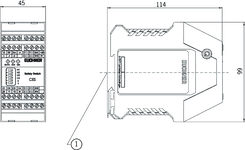
Dimensional drawings
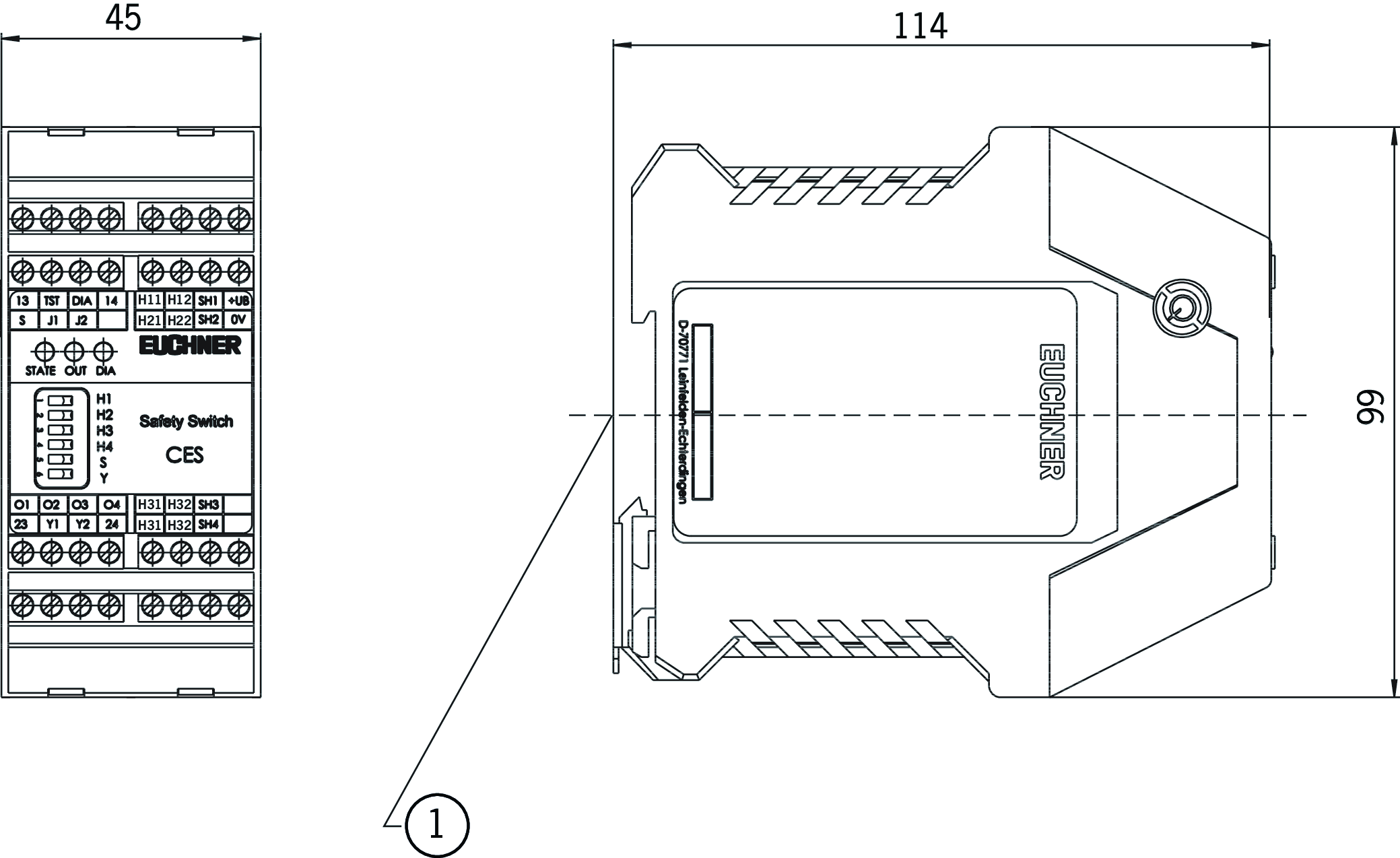
| 1 | Suitable for 35 mm mounting rail according to EN 60715 |
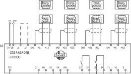
Connection examples
Műszaki adatok
Approvals


Workspace
| Repeat accuracy R | |
| according to EN 60947-5-2 | 10 % |
Operating and display elements
| LED display | |
| Diagnostics LED | |
| Status LED | |
| Safety outputs status |
| Item | Color | Extras | Note slide-in label | Version | Slide-in label | Switching element | Number | Designation1 | LED |
|---|---|---|---|---|---|---|---|---|---|
| Configuration setting for teach-in operation | DIP switches (H1, H2, H3, H4, S, Y) |
Electrical connection values
| Fuse | |
| external (operating voltage UB) | 0.25 ... 8 A |
| Connection cross section | |
| Screw terminals | 0.25 ... 2.5 mm² |
| Operating voltage DC | |
| UB | 21 ... 24 ... 27 V DC regulated, residual ripple<5% |
| EMC protection requirements | Acc. to EN IEC 60947-5-3 |
| Current consumption | |
| (with relay energized) | 150 mA (without taking into account the load currents at the monitoring outputs) |
| Current via feedback loop | 5 ... 8 ... 10 mA |
| Degree of contamination (external, according to EN 60947-1) | 2 |
| permissible resistance in feedback loop | max. 600 Ω |
| Inputs: start button S, test input TST | |
| Input voltage | |
| HIGH | 15 ... UB V DC |
| LOW | 0 ... 2 V DC |
| Input current | |
| HIGH | 5 ... 8 ... 10 mA |
| Monitoring outputs: diagnostics DIA, door monitoring outputs O1,O2,O3,O4 | |
| Output type | Semiconductor output, p-switching, short circuit-proof |
| Output voltage | 0.8 x UB ... UB V DC |
| Switching current | max. 20 mA |
| Safety contacts 13/14, 23/24 | |
| Fuse | |
| external (safety circuit) according to EN 60269-1 | 6 AgG or 6 A circuit breaker (characteristic B or C) |
| Output type | Relay contacts, floating |
| rated conditional short-circuit current | 100 A |
| Rated insulation voltage Ui | 250 V |
| Rated impulse voltage Uimp | 4 kV |
| Discrepancy time | |
| (between the operating points of both relays, with 4 active actuators) | max. 400 ms |
| Utilization category | |
| AC-15 | 230V 1.5A |
| DC-12 | 60V 0.3A |
| DC-12 | 30V 6A |
| DC-13 | 24V 1.2A |
| AC-12 | 60V 0.3A |
| AC-12 | 30V 6A |
| Switching load | |
| according to c UL us | Class 2 max. 30 V AC / Class 2 max. 60 V DC |
| Switching current | |
| at switching voltage AC/DC 17 ... 30 V | 15 ... 6000 mA |
| at switching voltage AC 17 ... 230 V | 15 ... 1500 mA |
| at switching voltage AC/DC 1 ... 60 V | 1 ... 300 mA (If a switching current>300 mA in conjunction with a switching voltage>15 V or an inductive or capacitive load is switched once using the relay outputs, it is no longer possible to reliably switch small currents (<15 mA) due to the contact erosion on the gold contacts.) |
Mechanical values and environment
| Connection type | Screw terminals |
| Number of read heads | Max. 4 read heads can be connected. |
| Ready delay | 10 ... 12 s (After the operating voltage is switched on, the relay outputs are switched off and the door monitoring outputs are set to LOW level during the ready delay. For visual indication of the delay, the green STATE LED flashes at a frequency of approx. 15 Hz.) |
| Switching frequency | max. 0.25 Hz (In case of monitoring with feedback loop, the actuators must remain outside the actuating range, e.g. with a door open, until the feedback loop is closed.) |
| Storage temperature | -25 ... 70 °C |
| Atmospheric humidity | |
| not condensing | max. 80 % rH |
| Mounting distance | |
| between evaluation units | min. 10 mm |
| Mounting type | Mounting rail TH 35 (EN IEC 60715) |
| Response time | |
| after change in the actuation status, 3 active actuators | max. 370 ms (Corresponds to the risk time according to EN 60947-5-3. This is the maximum OFF time for the safety outputs following removal of the actuator. In case of EMC interference in excess of the requirements in accordance with EN 60947-5-3, the OFF time can increase to max. 750 ms. After a brief actuation<0.8 s, the switch-on delay can increase to max. 3 s.) |
| after change in the actuation status, 4 active actuators | max. 450 ms (Corresponds to the risk time according to EN 60947-5-3. This is the maximum OFF time for the safety outputs following removal of the actuator. In case of EMC interference in excess of the requirements in accordance with EN 60947-5-3, the OFF time can increase to max. 750 ms. After a brief actuation<0.8 s, the switch-on delay can increase to max. 3 s.) |
| after change in the actuation status, 2 active actuators | max. 290 ms (Corresponds to the risk time according to EN 60947-5-3. This is the maximum OFF time for the safety outputs following removal of the actuator. In case of EMC interference in excess of the requirements in accordance with EN 60947-5-3, the OFF time can increase to max. 750 ms. After a brief actuation<0.8 s, the switch-on delay can increase to max. 3 s.) |
| Start button actuating duration (for Manual Start operating mode) | min. 250 ms |
| after change in the actuation status, 1 active actuator | max. 210 ms (Corresponds to the risk time according to EN 60947-5-3. This is the maximum OFF time for the safety outputs following removal of the actuator. In case of EMC interference in excess of the requirements in accordance with EN 60947-5-3, the OFF time can increase to max. 750 ms. After a brief actuation<0.8 s, the switch-on delay can increase to max. 3 s.) |
| Start button response delay (for Manual start operating mode) | 200 ... 300 ms |
| Degree of protection | IP20 |
| Ambient temperature | |
| at UB = 24 V DC | -20 ... 55 °C |
| Dwell time | min. 3 s (The dwell time is the time that the actuator must be outside the actuating range.) |
| Material | |
| Housing | Plastic PA6.6 |
| Safety contacts 13/14, 23/24 | |
| Number of safety contacts | 2 Relay with internally monitored contacts (To ensure safety, both safety outputs (13/14 and 23/24) must always be evaluated.) |
| Mechanical life | |
| Operating cycles (relay) | 10 x 10⁶ |
Characteristic values according to EN ISO 13849-1 and EN IEC 62061
| PL | Maximum SIL | PFHD | Category | Mission time | ||
|---|---|---|---|---|---|---|
| Monitoring of the guard position | Read head CES-A-L.. CEM-A-L.. | PL e | - | 1.9x10⁻⁸ | 4 | 20 y |
| Only applies for switching voltage 24V DC and switching current up to 0.1 A (max. switching cycles 760,000 1/y) OR up to 1 A (max. switching cycles 153,000 1/y ) OR up to 3 A (max. switching cycles 34,600 1/y) | ||||||
Miscellaneous
| Notices for UL approval | Operation only with UL Class 2 power supply or equivalent measures. |
In combination with read head CES-A-LNA-SC-077715, CES-A-LNA-05P-077806, CES-A-LNA-10P-077807, CES-A-LNA-05V-071845, CES-A-LNA-10V-071846, CES-A-LNA-15V-071847, CES-A-LNA-25V-071975, CES-A-LNA-15P-084682, CES-A-LCA-10V and actuator CES-A-BBA-071840, CES-A-BCA
| Actuator distance s | |
| Minimum distance for side approach direction | min. 3 mm |
| Switch-on distance | |
| with center offset m=0 | 15 mm (for surface mounting of the read head and the actuator) |
| Secured switch-off distance sar | max. 32 mm |
| Secured switching distance sao | |
| with center offset m=0 | min. 10 mm (for surface mounting of the read head and the actuator) |
| Switching hysteresis | 0.5 ... 2 mm (for surface mounting of the read head and the actuator) |
In combination with read head CES-A-LQA-SC and actuator CES-A-BBA-071840, CES-A-BCA
| Switch-on distance | |
| for side approach direction (distance in x direction 8 mm) | +/- 22 mm (for surface mounting of the read head and the actuator) |
| with vertical approach direction (center offset m = 0) | 15 mm (for surface mounting of the read head and the actuator) |
| Secured switch-off distance sar | max. 47 mm |
| Secured switching distance sao | |
| with vertical approach direction (center offset m = 0) | min. 10 mm (for surface mounting of the read head and the actuator) |
| for side approach direction (distance in x direction 8 mm) | min. +/- 18 mm (for surface mounting of the read head and the actuator) |
| Switching hysteresis | |
| for side approach direction (distance in x direction 8 mm) | 1 ... 1.8 mm (for surface mounting of the read head and the actuator) |
| with vertical approach direction (center offset m = 0) | 2 ... 3 mm (for surface mounting of the read head and the actuator) |
In combination with read head CES-A-LNA-SC-077715, CES-A-LNA-05P-077806, CES-A-LNA-10P-077807, CES-A-LNA-05V-071845, CES-A-LNA-10V-071846, CES-A-LNA-15V-071847, CES-A-LNA-25V-071975, CES-A-LNA-15P-084682, CES-A-LCA-10V
| Mounting distance | |
| between read heads | min. 50 mm |
In combination with read head CES-A-LMN-SC
| Mounting distance | |
| between read heads | min. 20 mm |
In combination with read head CES-A-LQA-SC
| Mounting distance | |
| between read heads | min. 80 mm |
In combination with read head CES-A-LMN-SC and actuator CES-A-BMB
| Actuator distance s | |
| Minimum distance for side approach direction | min. 1.2 mm |
| Switch-on distance | |
| with center offset m=0 | 5 mm (for surface mounting of the read head in steel) |
| Secured switch-off distance sar | max. 10 mm |
| Secured switching distance sao | |
| with center offset m=0 | min. 3.5 mm (for surface mounting of the read head in steel) |
| Switching hysteresis | 0.1 ... 0.3 mm (for surface mounting of the read head in steel) |
In combination with read head CES-A-LQA-SC and actuator CES-A-BQA
| Switch-on distance | |
| with vertical approach direction (center offset m = 0) | 23 mm (for surface mounting of the read head and the actuator) |
| for side approach direction (distance in x direction 10 mm) | +/- 28 mm (for surface mounting of the read head and the actuator) |
| Secured switch-off distance sar | max. 60 mm |
| Secured switching distance sao | |
| for side approach direction (distance in x direction 10 mm) | min. +/- 24 mm (for surface mounting of the read head and the actuator) |
| with vertical approach direction (center offset m = 0) | min. 16 mm (for surface mounting of the read head and the actuator) |
| Switching hysteresis | |
| with vertical approach direction (center offset m = 0) | 2 ... 3 mm (for surface mounting of the read head and the actuator) |
| for side approach direction (distance in x direction 10 mm) | 1 ... 1.3 mm (for surface mounting of the read head and the actuator) |
In combination with read head CES-A-LNA-SC-077715, CES-A-LNA-05P-077806, CES-A-LNA-10P-077807, CES-A-LNA-05V-071845, CES-A-LNA-10V-071846, CES-A-LNA-15V-071847, CES-A-LNA-25V-071975, CES-A-LNA-15P-084682, CES-A-LCA-10V and actuator CES-A-BDA-20
| Actuator distance s | |
| Minimum distance for side approach direction | min. 4 mm (on mounting in non-metallic environment) |
| Switch-on distance | |
| with center offset m=0 | 16 mm (on mounting in non-metallic environment) |
| Secured switch-off distance sar | max. 33 mm |
| Secured switching distance sao | |
| with center offset m=0 | min. 11 mm (on mounting in non-metallic environment) |
| Switching hysteresis | 0.5 ... 2 mm (on mounting in non-metallic environment) |
Tartozékok
CEM read heads
Read head CEM-A-LE05... with guard locking without guard lock monitoring with remanence

102821
CEM-A-LE05K-S1-10P
CEM-A-LE05K-S1-10P
- Read head with guard locking without guard lock monitoring
- Locking force 650 N
- With remanence
- Connection, CES evaluation unit: Cable 10 m, PUR
- Connection, solenoid operating voltage: M8 male plug
- Up to category 4 according to EN ISO 13849-1
094800
CEM-A-LE05K-S2
CEM-A-LE05K-S2
- Read head with guard locking without guard lock monitoring
- Locking force 650 N
- With remanence
- Up to category 4 according to EN ISO 13849-1
- Two safety screws M5x16 included

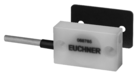
CES read heads


Letöltések
Teljes csomag
Minden fontos dokumentum letöltése egyetlen kattintással.
Tartalom:
- A használati utasítás és a használati utasítás vagy a rövid utasítás kiegészítései
- A használati utasítást kiegészítő adatlapok
- A megfelelőségi nyilatkozat
Teljes csomag letöltése (ZIP, 5,2 MB)
Egyedi dokumentumok
Declarations of conformity
EU-Konformitätserklärung
Dok. sz.
Változat
Nyelv
Méret
EU-Konformitätserklärung
Dok. sz.
EDC2077154
Változat
Nyelv
Méret
0,2 MB
UKCA-Konformitätserklärung

Dok. sz.
Változat
Nyelv
Méret
UKCA-Konformitätserklärung
Dok. sz.
EDC20001581
Változat
Nyelv
Méret
0,2 MB
Instructions
Operating instructions Non-contact safety system CES-A-AEA-02B/CES-A-AEA-04B (Unicode)


Dok. sz.
Változat
Nyelv
Méret
Operating instructions Non-contact safety system CES-A-AEA-02B/CES-A-AEA-04B (Unicode)
Dok. sz.
2084606
Változat
22-08/20
Nyelv
Méret
1,5 MB
Mode d'emploi Système de sécurité sans contact CES-A-AEA-02B/CES-A-AEA-04B (Unicode)
Dok. sz.
2084606
Változat
22-08/20
Nyelv
Méret
1,4 MB
Manual de instrucciones Sistema de seguridad sin contacto CES-A-AEA-02B/CES-A-AEA-04B (Unicode)
Dok. sz.
2084606
Változat
22-08/20
Nyelv
Méret
1,5 MB
Betriebsanleitung Berührungsloses Sicherheitssystem CES-A-AEA-02B/CES-A-AEA-04B (Unicode)
Dok. sz.
2084606
Változat
22-08/20
Nyelv
Méret
1,4 MB
Istruzioni di impiego Sistema di sicurezza senza contatto CES-A-AEA-02B/CES-A-AEA-04B (Unicode)
Dok. sz.
2084606
Változat
22-08/20
Nyelv
Méret
1,4 MB

Egyéb dokumentumok
Approvals and certificates
CCC

Dok. sz.
Változat
Nyelv
Méret
CCC
Dok. sz.
20001753
Változat
Nyelv
Méret
0,0 MB
S-Mark

Dok. sz.
Változat
Nyelv
Méret
S-Mark
Dok. sz.
Változat
Nyelv
Méret
0,8 MB
WEEE

Dok. sz.
Változat
Nyelv
Méret
WEEE
Dok. sz.
ECO20001806
Változat
Nyelv
Méret
0,1 MB
c UL us


Dok. sz.
Változat
Nyelv
Méret
c UL us
Dok. sz.
Változat
Nyelv
Méret
0,2 MB
c UL us
Dok. sz.
Változat
Nyelv
Méret
0,2 MB

Rendelési adatok
| Rend. sz. | 072000 |
| Cikk neve | CES-A-AEA-04B |
| Súly | 0,34kg |
| Global Trade Item Number (GTIN) | 4047048000216 |
| Vámtarifaszám | 85364110 |
| ECLASS | 27-27-24-03 Safety-related transponder switch |