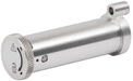
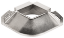
CET3-AP-CRA-CH-50X-SA-121579 (Rend. sz. 121579)
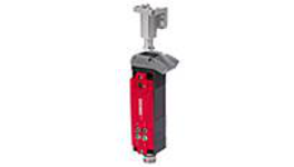
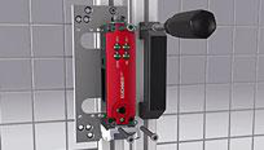
Safety switch with guard locking CET-AP-..., RFID, plug connector(s) M12
- Closed-circuit current principle
- Multicode
- Monitoring output guard locking OUT
- Monitoring output door position OUT D
- Plug connector M12, 8-pin
Ismertetés
Approach direction
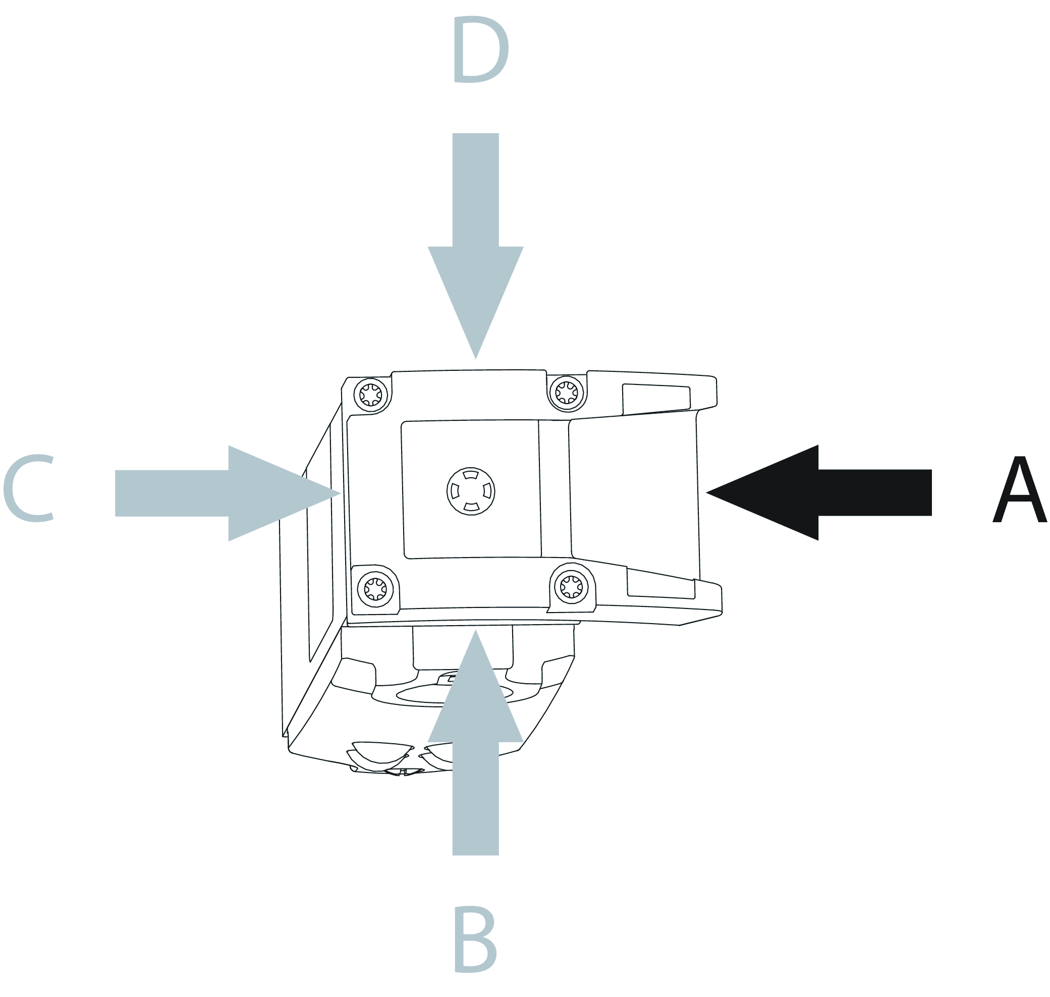
Horizontal
Can be adjusted in 90° steps
Guard locking principle
Power to unlock: On a guard with guard locking based on the closed-circuit current principle, the guard is locked by spring force until the guard locking solenoid is supplied with power. Unlocking is by solenoid force. The term mechanical guard locking is also used.
Multicode evaluation
The system checks whether the actuator type is one that can be recognized by the system (multicode evaluation). The system has a low coding level. Every suitable actuator is recognized by the switch.
Safety characteristics
Thanks to two redundant safety outputs (semiconductor outputs) with internal monitoring, the device is suitable for:
- Category 4 /PL e according to EN 13849-1
- SIL 3 according to EN IEC 62061 Table 4
The OSSD outputs used check their function for short circuits and short circuits with test pulses.
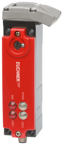
LED indicator
LED STATE | Status LED |
DIA LED | Diagnostics LED |
LED 1 rd | illuminates when the solenoid is energized |
LED 2 gn | illuminates when door is closed |
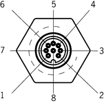
Terminal assignment
| Plug connector (view of connection side) | Pin | Designation | Function | Connecting cable conductor coloring |
|---|---|---|---|---|
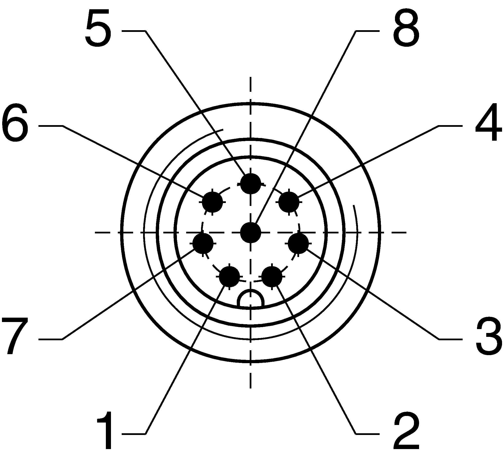 | 1 | UCM | Solenoid operating voltage, 24 V DC | WH |
| 2 | UB | Electronics operating voltage, 24 V DC | BN | |
| 3 | OA | Safety output, channel A | GN | |
| 4 | OB | Safety output, channel B | YE | |
| 5 | OUT | Monitoring output | GY | |
| 6 | OUT D | Door position monitoring output | PK | |
| 7 | 0 V UB | Electronics operating voltage, 0 V DC | BU | |
| 8 | 0V UCM | Solenoid operating voltage, 0 V DC | RD |
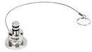
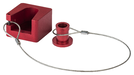
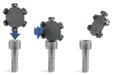
Accessories required
Actuator is not included.
The safety switch can only be actuated in conjunction with the actuators provided for this purpose.
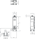


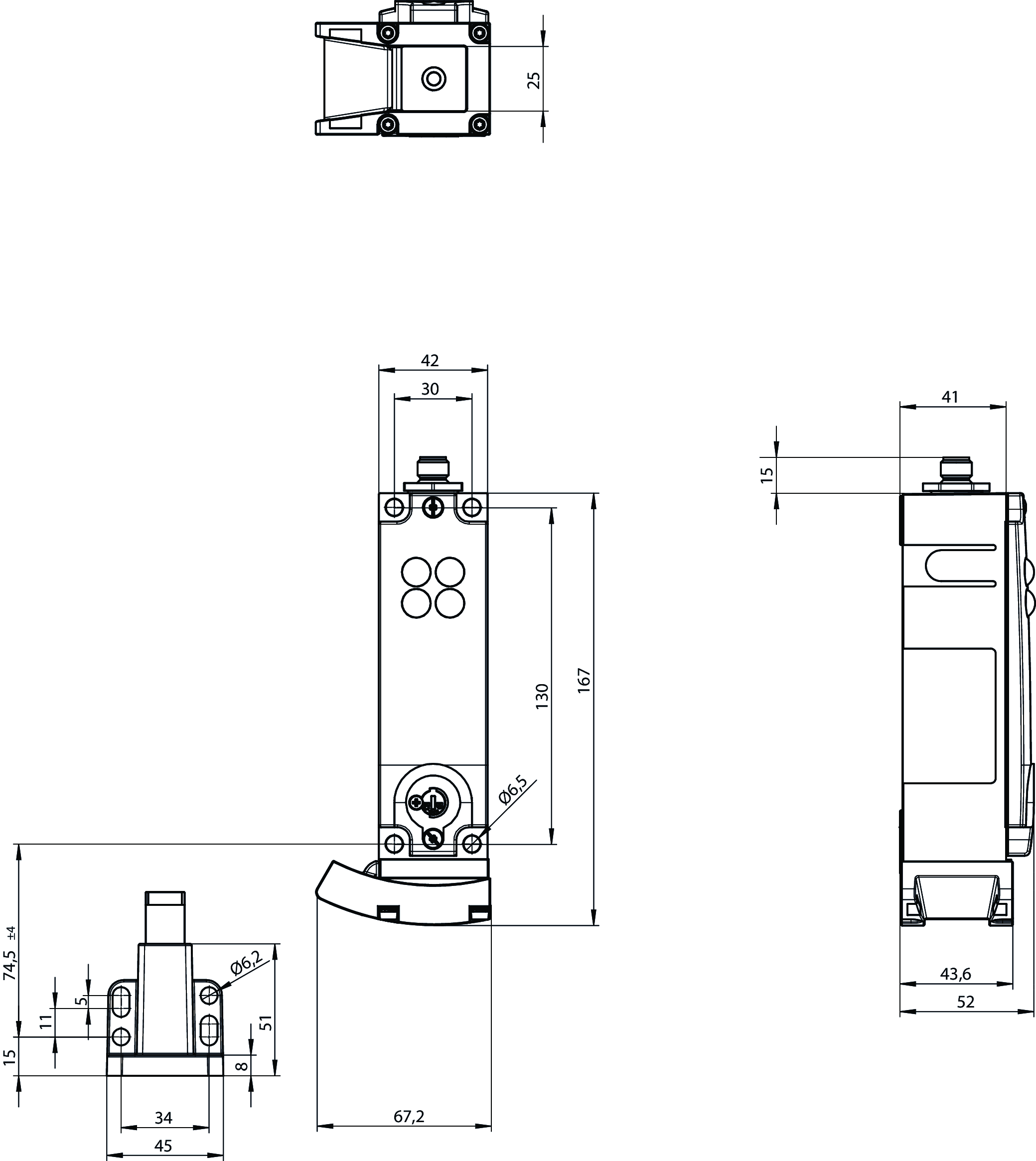
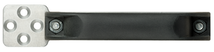
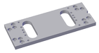
Dimensional drawings
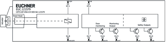
Connection examples
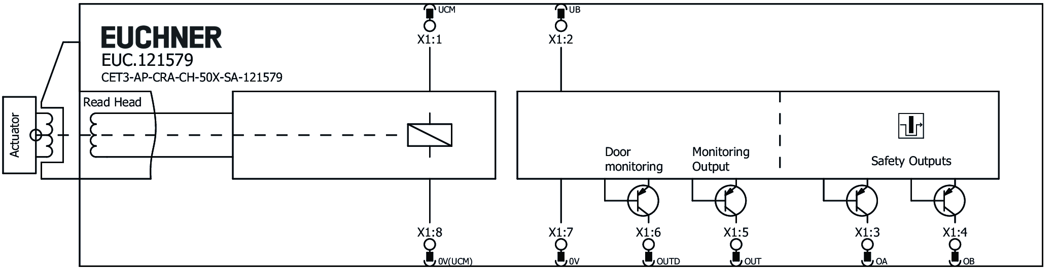
Connection examples

Műszaki adatok
Approvals

Workspace
| Repeat accuracy R | 10 % |
Electrical connection values
| Fuse | |
| external (operating voltage UB) | 0.25 ... 8 A |
| external (solenoid operating voltage UCM) | 0.5 ... 8 A |
| Power consumption | |
| Solenoid | 11 W |
| Connecting cable | 30V DC, 2A (for UL requirement UL category code (CYJV/CYJV7)) |
| Operating voltage DC | |
| LED | 24 V DC -15% V DC ... +10% V DC |
| UB | 24 V DC -15% ... +15% reverse polarity protected, regulated, residual ripple<5%, PELV (The device tolerates voltage interruptions of up to 5 ms) |
| EMC protection requirements | Acc. to EN IEC 60947-5-3 |
| Utilization category | |
| DC-13 | 24V 200mA (Caution: outputs must be protected with a free-wheeling diode in case of inductive loads) |
| Solenoid operating voltage DC | |
| UCM | 24 V DC -15% ... +10% reverse polarity protected, regulated, residual ripple<5%, PELV |
| Solenoid duty cycle | 100 % |
| Risk time according to EN 60947-5-3 | max. 400 ms |
| Switching load | |
| according to UL | 24V DC, Class 2 (For alternatives, see operating instructions) |
| Safety class | III |
| Current consumption | |
| ICM | 450 mA |
| IB | 80 mA |
| Test pulse duration | max. 0.3 ms (Applies to a load with C<= 30nF and R<= 20kOhm) |
| Degree of contamination (external, according to EN 60947-1) | 3 |
| Monitoring output OUT D | |
| Output type | p-switching, short circuit-proof |
| Output voltage | |
| OUT D | 0.8xUB ... UB V DC |
| Switching current | |
| OUT D | 1 ... 50 mA |
| Switching delay from state change | max. 700 ms |
| Monitoring output OUT | |
| Output type | p-switching, short circuit-proof |
| Output voltage | |
| OUT | 0.8xUB ... UB V DC |
| Switching current | |
| OUT | 1 ... 50 mA |
| Switching delay from state change | max. 400 ms |
| Safety outputs OA / OB | |
| Output type | 2 semiconductor outputs, p-switching, short circuit-proof |
| Output voltage | |
| HIGH U(OA,OB) | UB-1.5V ... UB V DC |
| LOW U(OA,OB) | 0 ... 1 V DC |
| Discrepancy time | |
| both safety outputs | max. 10 ms |
| Turn-on time | 400 ms |
| Off-state current Ir | max. 0.25 mA |
| Switching current | |
| per safety output OA / OB | 1 ... 200 mA |
Mechanical values and environment
| Anfahrgeschwindigkeit | max. 20 m/min |
| Connection type | 1 plug connector M12, 8-pin |
| Ready delay | 1 s |
| Installation orientation | any |
| Switching frequency | max. 0.5 Hz |
| Degree of freedom X | ±5 mm |
| Degree of freedom Y | ±5 mm |
| Degree of freedom Z | ±4 mm |
| Storage temperature | -25 ... 70 °C |
| Mechanical life | 2 x 10⁶ |
| Shock and vibration resistance | Acc. to EN IEC 60947-5-3 |
| Degree of protection | IP67 (In the inserted and screwed tight state) |
| Ambient temperature | |
| at UB = 24 V DC | -20 ... 55 °C |
| Material | |
| Ramp | Stainless steel |
| Safety switch housing | Die-cast aluminum |
| Locking force Fmax | 6500 N |
| Locking force FZh | 5000 N (FZH = FMAX/1.3) |
| Guard locking principle | Closed-circuit current principle |
Characteristic values according to EN ISO 13849-1 and EN IEC 62061
| PL | Maximum SIL | PFHD | Category | Mission time | |
|---|---|---|---|---|---|
| Guard lock monitoring | PL e | - | 3.1x10⁻⁹ | 4 | 20 y |
| PL | Maximum SIL | Category | Mission time | |
|---|---|---|---|---|
| Control of guard locking | Depending on external control of guard locking | 20 y | ||
Miscellaneous
| Notices for UL approval | Operation only with UL Class 2 power supply or equivalent measures; see operating instructions |
Tartozékok


AM-C-SW4-V3-161344
- Plastic inserts for hexagon socket screws a/f 4
- Efficient protection against tampering for safety switch mounting
- The packaging includes inserts for 18 screws
AM-C-SW5-V3-161348
- Plastic inserts for hexagon socket screws a/f 5
- Efficient protection against tampering for safety switch mounting
- The packaging includes inserts for 18 screws

Letöltések
Teljes csomag
Minden fontos dokumentum letöltése egyetlen kattintással.
Tartalom:
- A használati utasítás és a használati utasítás vagy a rövid utasítás kiegészítései
- A használati utasítást kiegészítő adatlapok
- A megfelelőségi nyilatkozat
Egyedi dokumentumok


Egyéb dokumentumok


Rendelési adatok
| Rend. sz. | 121579 |
| Cikk neve | CET3-AP-CRA-CH-50X-SA-121579 |
| Súly | 1,267kg |
| Vámtarifaszám | 85365019000 |
| ECLASS | 27-27-24-05 Safety-related transponder switch with guardlocking |

Műszaki támogatás
Do you have technical questions about our products, their possible use or applications? Our experts will be happy to help.
EUCHNER Magyarország Kft.
+36 1 919 0855
info@euchner.hu